Single-acting plunger cylinder hydraulic system

A technology of hydraulic system and plunger cylinder, which is applied in the field of electromechanical-hydraulic integrated control equipment, can solve the problems of increasing the external dimension and self-weight of the hydraulic system, the volume and self-weight of the solenoid valve, and increasing the working pressure of the system, so as to reduce the self-weight and simplify the Structure, the effect of improving the oil return speed

Active Publication Date: 2020-03-17
SOUTHWEST JIAOTONG UNIV
View PDF5 Cites 2 Cited by
  • Summary
  • Abstract
  • Description
  • Claims
  • Application Information

AI Technical Summary

Problems solved by technology

Adding a recovery spring will generate additional load, which will increase the working pressure of the system; if the load is recovered from the outside, since the system is mostly controlled by a servo valve, the return oil of the plunger cylinder is returned through the servo valve, and the retraction speed of the plunger cylinder depends on Due to the pressure difference, the diameter of the servo valve is small, and the large oil return resistance seriously affects the recovery action
At the same time, the size and weight of the solenoid valve are larger, which increases the overall size and weight of the hydraulic system.

Method used


Image

  • Single-acting plunger cylinder hydraulic system
  • Single-acting plunger cylinder hydraulic system
  • Single-acting plunger cylinder hydraulic system

Examples


Embodiment Construction

[0019] The present invention will be further described below in conjunction with the accompanying drawings and specific embodiments.

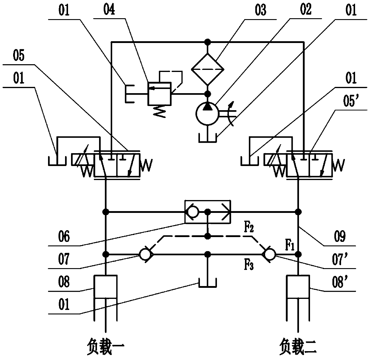
[0020] Such as figure 1 As shown, the hydraulic system is mainly composed of hydraulic oil tank 01, hydraulic pump 02, filter 03, overflow valve 04, left two-position three-way reversing valve 05, right two-position three-way reversing valve 05', shuttle valve 06 , the left hydraulic control check valve 07, the right hydraulic control check valve 07', the left single-acting plunger rod 08, the right single-acting plunger rod 08' and the hydraulic oil pipe 09.

[0021] The hydraulic oil tank 01 is connected with the hydraulic pump 02, and the whole system supplies hydraulic oil to various places through the hydraulic pump 02 driven by the motor. The outlet of the hydraulic pump 02 is equipped with a relief valve 04 connected to the hydraulic oil tank 01 to ensure that the system pressure does not exceed the design value . The hydraulic pump 02...


PUM


Abstract

The invention discloses a single-acting plunger cylinder hydraulic system. A hydraulic oil tank is connected with an inlet of a hydraulic pump, an outlet of the hydraulic pump is simultaneously connected with oil inlets of left-side and right-side two-position three-way reversing valves, and oil return openings of the left-side and right-side two-position three-way reversing valves are respectively connected with the hydraulic oil tank; an oil outlet of the left-side two-position three-way reversing valve is simultaneously connected with an inlet of a left-side hydraulic control one-way valveand an oil port of a left-side single-acting plunger cylinder and is further connected with one inlet of a shuttle valve; a valve oil outlet of the right-side two-position three-way reversing valve issimultaneously connected with an inlet of a right-side hydraulic control one-way valve and an oil port of a right-side single-acting plunger cylinder and is further connected with the other inlet ofthe shuttle valve; an outlet of the shuttle valve is simultaneously connected with hydraulic control ports of the left-side hydraulic control one-way valve and the right-side hydraulic control one-wayvalve; outlets of the left-side hydraulic control one-way valve and the right-side hydraulic control one-way valve are connected with the hydraulic oil tank; and the effective hydraulic area of the inlets of the hydraulic control one-way valves is larger than the effective hydraulic area of the hydraulic control ports. The complexity of a traditional hydraulic system is reduced, the external dimensions of elements and the system are reduced, and the structure is more compact.

Description

technical field [0001] The invention relates to the technical field of electromechanical-hydraulic integrated control equipment, in particular to a single-acting plunger-cylinder hydraulic system. Background technique [0002] The system consisting of power components, actuators, control components, auxiliary components (accessories) and hydraulic oil is called a hydraulic system. Because the hydraulic system has the advantages of large driving force (suitable for heavy-duty direct drive), various speed control methods, self-lubricating, self-cooling, long life, and easy realization of safety protection, it is widely used and has an irreplaceable role in the field of electromechanical-hydraulic integration. status. [0003] In a hydraulic system with a single-acting plunger cylinder, the single-acting plunger cylinder realizes the advancement of the plunger rod through external oil intake, but its recovery action requires an additional external load to return the oil. Ther...

Claims


Application Information

Patent Timeline
Patent Type & Authority Applications(China)
IPC IPC(8): F15B11/16F15B13/06
CPCF15B11/16F15B13/027F15B13/06
Inventor 邓斌李志伟何沛恒徐新雷越左荣王奇
Owner SOUTHWEST JIAOTONG UNIV
Why Eureka
Try Eureka