Self-suction CEMS multi-point flue gas sampling device and control method

A flue gas sampling and self-priming technology, applied in sampling devices, sampling, measuring devices, etc., can solve problems such as air preheater blockage, flue gas turbulence, and difficulty in controlling denitrification and ammonia injection of thermal power units

Inactive Publication Date: 2020-03-17
HUANENG LUOYUAN POWER GENERATION CO LTD
View PDF5 Cites 3 Cited by
  • Summary
  • Abstract
  • Description
  • Claims
  • Application Information

AI Technical Summary

Problems solved by technology

On the one hand, due to the slow extraction of flue gas by the sampling pump with limited output, and the long sampling pipeline, etc., the flue gas sampling time is long, and the CEMS measurement lags for as long as 1-2 minutes; on the other hand, due to the straight pipe section of the flue Short, uneven flue gas flow field, serious flue gas turbulence and other reasons, resulting in non-representative flue gas sampling, CEMS measurement can not truly reflect the flue gas content
The above two reasons make it difficult to control the denitrification and ammonia injection of thermal power units
In order to avoid excessive emissions, most power plants currently adopt the control method of excessive ammonia injection, which greatly increases the cost of ammonia injection, and at the same time, there is a risk of air preheater blockage

Method used


Image

  • Self-suction CEMS multi-point flue gas sampling device and control method
  • Self-suction CEMS multi-point flue gas sampling device and control method
  • Self-suction CEMS multi-point flue gas sampling device and control method

Examples


Embodiment Construction

[0029] In order to make the features and advantages of this patent more obvious and easy to understand, the following specific examples are given together with the accompanying drawings and described in detail as follows:

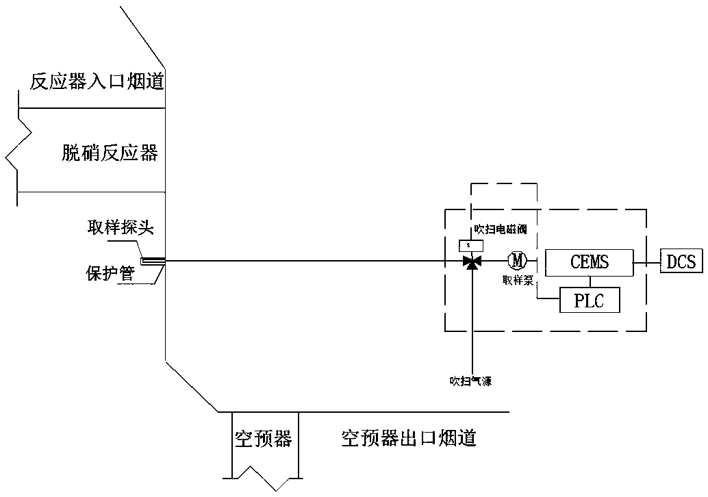
[0030] Such as figure 1 As shown, in the existing CEMS flue gas sampling devices produced by major CEMS equipment manufacturers, the depth of the sampling pipe inserted into the flue is less than 2m, and the flue gas extraction relies on the sampling pump to provide power extraction.

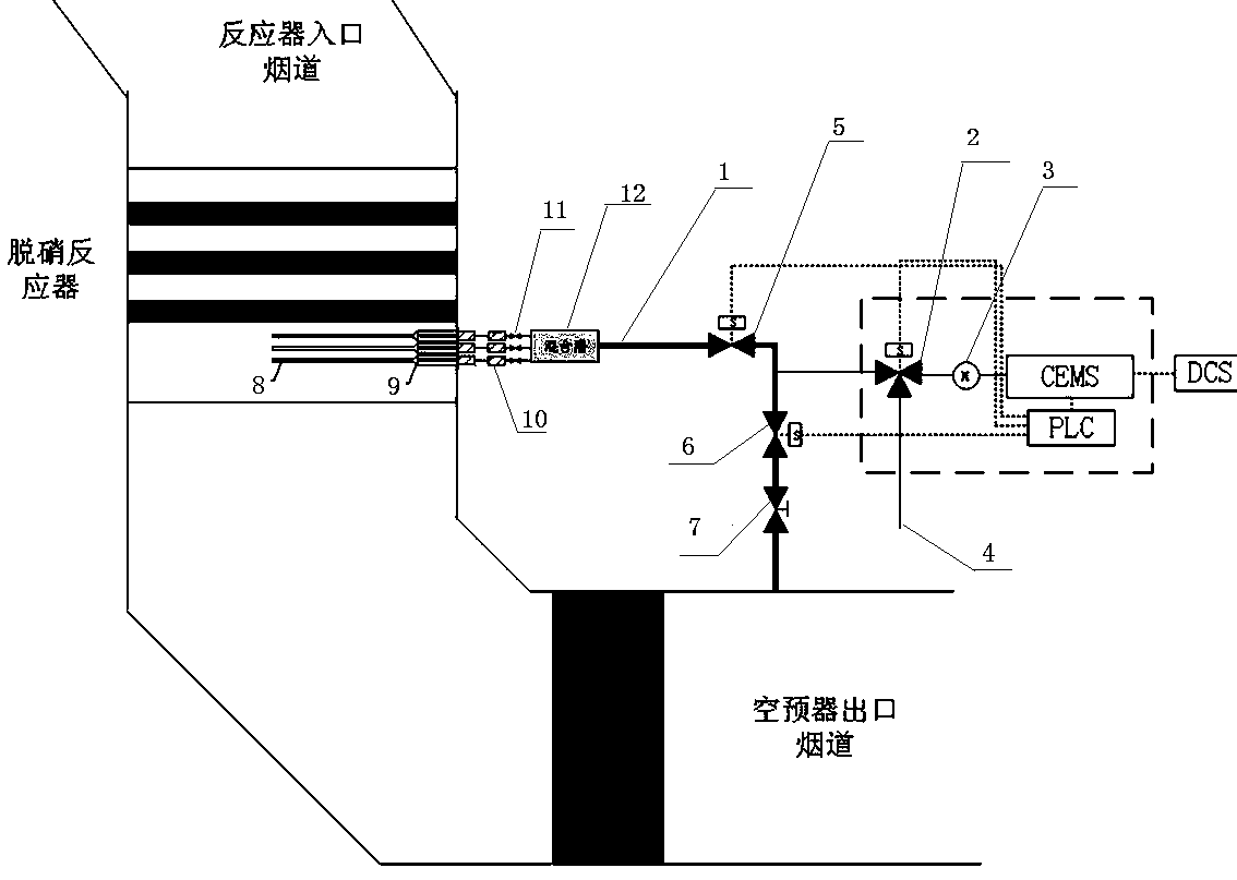
[0031] Such as figure 2 , image 3 As shown, in the solution provided in this embodiment, in order to overcome the problems of long sampling time and measurement lag, the sampling pipe 1 is connected to the outlet flue of the air preheater, and the pressure ratio of the outlet flue of the air compressor to the outlet flue of the denitrification reactor is used. The channel pressure is 1-2KPa lower, and the pressure difference is much larger than the pressure head of the sa...


PUM


Abstract

The invention provides a self-suction CEMS multi-point flue gas sampling device and a control method, and aims to overcome the problems of long sampling time and measurement lag. A sampling pipe is connected to the outlet flue of an air preheater. The characteristic that the outlet flue pressure of the air compressor is 1-2KPa lower than the outlet pressure of a denitration reactor is utilized, the pressure difference is far greater than that of the pressure head of a sampling pump and the flue gas can naturally and quickly flow by virtue of the pressure difference so that the quick replacement of the flue gas in the sampling pipe is realized, the sampling lag is eliminated, and the flue gas sampling speed not only depends on the sampling pump, but also depends on the natural circulation of the flue gas by virtue of the flue gas pressure difference between the denitration outlet and the outlet of the air pre-heater. Furthermore, a sampling branch pipe is connected before the pipeline of the sampling pipe passes through the sampling pump of the CEMS, the flue gas is extracted by the sampling pump to enter a CEMS analyzer and experimental verification shows that the sampling time ofthe mode can be shortened by more than 90%.

Description

technical field [0001] The invention relates to the field of thermal control instruments, in particular to a self-priming CEMS multi-point flue gas sampling device and a control method. Background technique [0002] For the emission control of pollutants in thermal power plants, the control of NOx has always been a difficult point. On the one hand, due to the slow extraction of flue gas by the sampling pump with limited output, and the long sampling pipeline, etc., the flue gas sampling time is long, and the CEMS measurement lags for as long as 1-2 minutes; on the other hand, due to the straight pipe section of the flue Short, uneven flue gas flow field, severe flue gas turbulence and other reasons, resulting in non-representative flue gas sampling, CEMS measurement can not truly reflect the flue gas content. The above two reasons make it difficult to control the denitrification and ammonia injection of thermal power units. In order to avoid excessive emissions, most power...

Claims


Application Information

Patent Timeline
Patent Type & Authority Applications(China)
IPC IPC(8): G01N1/24
CPCG01N1/2205G01N1/2258
Inventor 潘喜良林昇王冰礁黄学辉黄秀晶
Owner HUANENG LUOYUAN POWER GENERATION CO LTD
Why Eureka
Try Eureka