
Reactor core cooling system and reactor core cooling method

A core cooling and core technology, applied in cooling devices, reactors, reducing greenhouse gases, etc., can solve the problem that the cooling process cannot run normally, and achieve the effect of preventing dry burning and saving coolant

Active Publication Date: 2020-03-17
中广核(北京)仿真技术有限公司 +2
View PDF6 Cites 1 Cited by
  • Summary
  • Abstract
  • Description
  • Claims
  • Application Information

AI Technical Summary

Problems solved by technology

However, when the entire plant loses power, the entire cooling process cannot function properly

Method used


Image

  • Reactor core cooling system and reactor core cooling method
  • Reactor core cooling system and reactor core cooling method

Examples


Embodiment 1

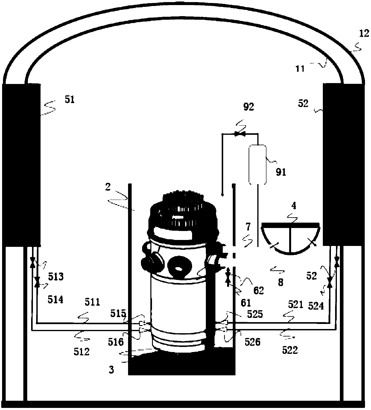
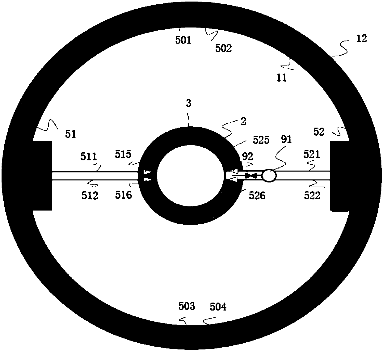
[0031] refer to Figure 1-2 , figure 1 is a cross-sectional view, figure 2 is a top view. In a specific embodiment, the double-sided cooling system of the pressure vessel includes: a double-layer containment vessel, a reactor sump 2, a pressure vessel 3, and a steam generator 4 (only the inlet and outlet chambers of the steam generator 4 are shown in the figure).

[0032] Wherein, the longitudinal section of the double-layer containment vessel is inverted U-shaped, the double-layer containment vessel includes a containment vessel inner wall 11 and a containment vessel outer wall 12, and at least A cooling water chamber for storing coolant. When there are multiple cooling water chambers, the multiple cooling water chambers are arranged along the circumferential direction of the double containment shell. In this embodiment, two left and right cooling water chambers 51 and 52 are formed between the containment inner wall 11 and the containment outer wall 12. It can be underst...

Embodiment 2

[0041] Based on the same inventive concept as the first embodiment, the second embodiment discloses a core cooling method, which is implemented based on the system in the first embodiment. The method of this embodiment includes:

[0042] In the event of a plant-wide blackout in a nuclear power plant, perform the following actions:

[0043] S100. Open the special release valve and water injection valve for the pressurizer, and the water injection pipeline injects coolant into the pressure vessel and the core in a passive manner, and the release pipeline transfers steam, steam-water mixture or coolant from the core into the heat pipe section discharge into said reactor sump;

[0044] S200. When the water level of the reactor water pit rises to a first height, perform step S300; when the water level of the reactor water pit drops to a second height, it is recommended that the first height be taken from the reactor water pit The height corresponding to the top position of , the ...


PUM


Abstract

The invention discloses a reactor core cooling system and a reactor core cooling method. The system comprises a double-wall containment, a reactor water storage pit, a pressure vessel and a steam generator, the double-wall containment comprises a containment inner wall and a containment outer wall, and at least one cooling water chamber for storing a coolant is formed between the inner wall and the outer wall. When a whole nuclear power plant is powered off, a special release valve for a pressure stabilizer and a water injection valve are opened, and a water injection pipeline injects the coolant into the pressure vessel, a release pipeline discharges steam, a steam-water mixture or a coolant, entering a heat pipe section from a reactor core, into the reactor water storage pit; when the water level of the reactor water storage pit rises to a first height, the water injection valve is closed, a backflow injection valve is opened, and a part of the coolant in the reactor water storage pit flows back into the pressure vessel and the reactor core through the backflow injection pipeline; and when the water level of the reactor water storage pit is reduced to a second height, the water injection valve is opened, and the backflow injection valve is closed, so that the simultaneous cooling effect inside and outside the pressure vessel can be realized, and the coolant is saved.

Description

technical field [0001] The invention relates to the field of nuclear power, in particular to a core cooling system and method. Background technique [0002] Nuclear power plants rely on reactor pressure vessels, steam generators, and steam turbines for cooling. The first loop connects the reaction vessel and the steam generator, and the second loop connects the steam generator and the steam turbine. The cooling process of the nuclear power plant during normal power supply is as follows: when the cooling water in the first circuit flows through the reactor pressure vessel and the core, it absorbs the heat of the nuclear reaction and the temperature rises; when it flows through the steam generator, it transfers heat to the water in the second circuit, and at the same time When the temperature drops, it flows back to the reactor pressure vessel and the core to absorb heat again; when the water in the second circuit flows through the steam generator, it absorbs the heat of the ...

Claims


Application Information

Patent Timeline
IPC IPC(8): G21C15/18
CPCG21C15/18Y02E30/30
Inventor 骆邦其姜夏岚章旋
Owner 中广核(北京)仿真技术有限公司
Learn More