
Synchronous rectification control circuit, isolated power supply conversion circuit and control method

A synchronous rectification and control circuit technology, which is applied in the direction of high-efficiency power electronic conversion, DC power input conversion to DC power output, AC power input conversion to DC power output, etc., can solve the abnormal operation of the flyback circuit, cannot be compatible with CCM, and is reliable Low performance and other issues to achieve the effect of avoiding common use, improving reliability, and improving shutdown speed

Pending Publication Date: 2020-03-20
杭州必易微电子有限公司
View PDF0 Cites 10 Cited by
  • Summary
  • Abstract
  • Description
  • Claims
  • Application Information

AI Technical Summary

Problems solved by technology

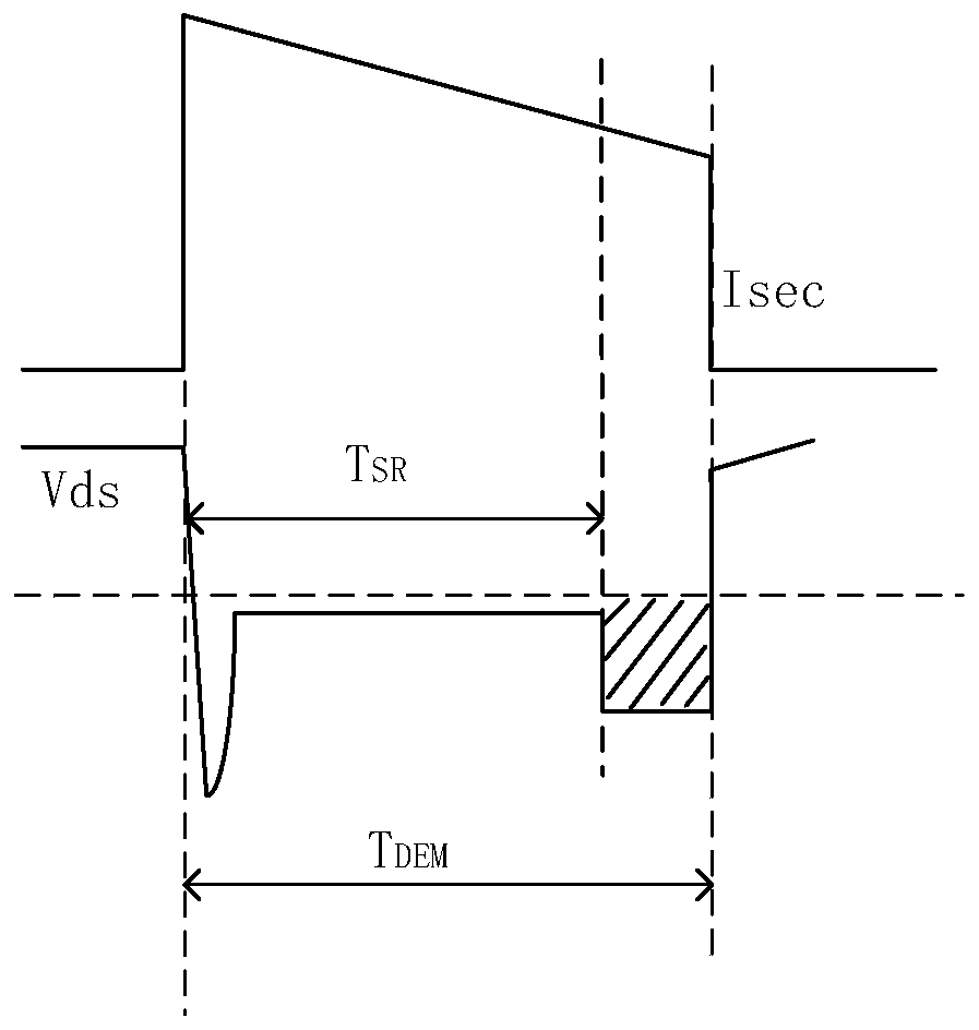
[0004] image 3 It is a schematic diagram of the waveform of the existing predictive SR shutdown method; please refer to image 3 , the predictive SR turn-off method obtains the turn-off point of the SR MOSFET through prediction. The disadvantage is that the dynamic process may be common, that is, the primary side power switch tube and the secondary side rectifier tube will have a common state, so that the work of the flyback circuit Abnormal, low reliability
[0005] Figure 4 It is a schematic diagram of the waveform of the SR shutdown method using the voltage detection shutdown method; please refer to Figure 4 , the voltage detection shutdown method detects the voltage across the MOSFET. When the voltage Vds between the drain and the source reaches a certain threshold Vth_off, the MOSFET is turned off. The disadvantage is that it is not compatible with CCM and the efficiency is low.

Method used


Image

  • Synchronous rectification control circuit, isolated power supply conversion circuit and control method
  • Synchronous rectification control circuit, isolated power supply conversion circuit and control method
  • Synchronous rectification control circuit, isolated power supply conversion circuit and control method

Examples


Embodiment Construction

[0048] Preferred embodiments of the present invention will be described in detail below in conjunction with the accompanying drawings.

[0049] In order to further understand the present invention, the preferred embodiments of the present invention are described below in conjunction with examples, but it should be understood that these descriptions are only to further illustrate the features and advantages of the present invention, rather than limiting the claims of the present invention.

[0050] The description in this part is only for several typical embodiments, and the present invention is not limited to the scope of the description of the embodiments. The mutual replacement of the same or similar prior art means and some technical features in the embodiments is also within the scope of the description and protection of the present invention.

[0051] "Coupling" or connection in the specification includes both direct connection and indirect connection, such as connection ...


PUM


Abstract

The invention discloses a synchronous rectification control circuit, an isolated power supply conversion circuit and a control method, the synchronous rectification control circuit can be coupled witha synchronous rectification transistor and can send a control signal to the synchronous rectification transistor; the synchronous rectification control circuit comprises a comparison circuit, a drivecircuit, a signal adjusting circuit and a conduction voltage drop adjusting circuit. The input end of the comparison circuit is respectively coupled with the synchronous rectification transistor andat least one reference signal, and the output end of the comparison circuit is respectively coupled with the drive circuit and the signal conditioning circuit; the output end of the drive circuit is coupled with the synchronous rectification transistor and used for sending a control signal to the synchronous rectification transistor according to the signal output by the comparison circuit; the output end of the signal adjusting circuit is coupled with the comparison circuit and used for adjusting a set reference signal in the at least one reference signal according to the signal output by thecomparison circuit. According to the invention, accurate turn-off of the synchronous rectification transistor can be realized, the turn-off speed can be improved, and the reliability of the circuit isimproved.

Description

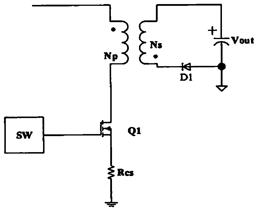
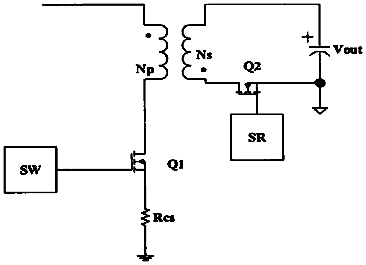
technical field [0001] The invention belongs to the technical field of electronic circuits and relates to a control circuit, in particular to a synchronous rectification control circuit, an isolated power conversion circuit and a control method. Background technique [0002] Synchronous rectification technology (Synchronous Rectification, referred to as SR) is a MOSFET (Metal-Oxide-Semiconductor Field-Effect Transistor, Metal-Oxide-Semiconductor Field-Effect Transistor, referred to as Metal-Oxide Semiconductor Field-Effect Transistor) to replace the rectifier diode to reduce rectification loss At present, it has been widely used in industrial power supply, consumer electronics and other fields. figure 1 It is a Flyback architecture diagram using diodes for secondary side rectification, figure 2 It is a Flyback architecture diagram using SR for secondary side rectification. Replacing rectification diodes with synchronous rectification MOSFETs with very low on-state resista...

Claims


Application Information

Patent Timeline
IPC IPC(8): H02M7/217H02M3/335
CPCH02M7/217H02M3/33592Y02B70/10
Inventor 张波文鹏
Owner 杭州必易微电子有限公司
Learn More