Crusher for construction waste

A technology of construction waste and crusher, which is applied in the direction of separating solids from solids with airflow, solid separation, grain treatment, etc., can solve the problem of large land expropriation fees, garbage removal and transportation costs, construction funds, wood waste mixed with cement blocks and iron Nails, lime sand flying environment and other problems, to achieve the effect of improving recycling efficiency, improving sharpness, and improving crushing efficiency

Active Publication Date: 2020-03-24
上海筱启新能源科技集团有限公司
View PDF8 Cites 5 Cited by
  • Summary
  • Abstract
  • Description
  • Claims
  • Application Information

AI Technical Summary

Problems solved by technology

[0005] In order to make up for the deficiencies of the existing technology, most of the construction waste is transported to the suburbs or villages by the construction unit without any treatment, and is piled in the open air or landfilled, which consumes a lot of construction funds such as land acquisition fees, garbage removal and transportation fees, and at the same time , problems such as dust, dust and sand flying in the process of cleaning and stacking have caused serious environmental pollution. After the wooden waste is piled up at the construction site, it is difficult to clean and transport quickly because of the different lengths. The wooden waste is often mixed with cement blocks. and iron nails and other impurities, it is difficult to recycle the problem, a kind of crusher for construction waste proposed by the present invention

Method used


Image

  • Crusher for construction waste
  • Crusher for construction waste
  • Crusher for construction waste

Examples


Embodiment approach

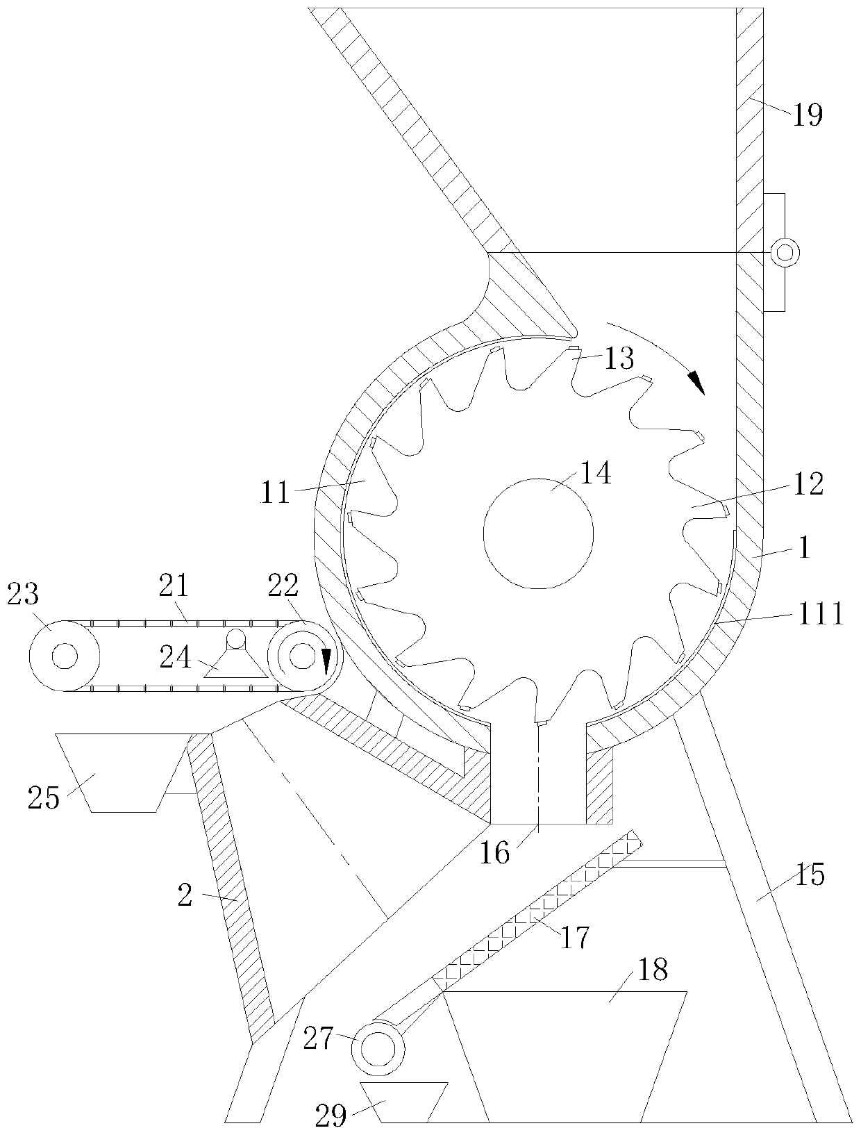
[0026] As an embodiment of the present invention, a funnel-shaped separation bucket 2 is provided on one side of the feeding hole 16, and the axis of the separation bucket 2 is perpendicular to the top surface of the screen 17; the top of the separation bucket 2 is provided with a conveyor belt 21, The conveyor belt 21 is tensioned and driven by the driving wheel 22 and the driven wheel 23, both of which are rotationally connected with the casing 1; the driving wheel 22 is driven by the No. 2 motor, and the No. 2 motor is connected to the power supply through the controller The conveyer belt 21 is made of air-permeable steel wire mesh, and the corresponding position of the middle part of the conveyer belt 21 and the top opening of the separation bucket 2 is provided with an air extraction funnel 24, and the air extraction funnel 24 is communicated with the air extractor, and the air extractor is connected by a controller Power supply; the exhaust port of the air extractor commu...


PUM


Abstract

The invention belongs to the technical field of construction waste treatment, and particularly relates to a crusher for construction waste. The crusher comprises a machine shell, wherein a crushing cavity is formed in the machine shell, and a crushing wheel is rotationally connected in the crushing cavity; a supporting rod is arranged at the bottom of the machine shell, a discharging hole is formed in the bottom of the crushing cavity, an inclined screen is arranged below the discharging hole, and the screen is fixedly connected with the supporting rod through a support; the lower portion of the screen is provided with a first hopper for collecting concrete particles, a feeding hopper is hinged to the upper portion of the machine shell, the height of the crusher is reduced after the feeding hopper is turned over, the transportation is convenient, the feeding hopper is large at the upper portion and is small at the lower portion, and the side wall on one side of the feeding hopper is vertically arranged and is tangent to the crushing cavity. According to the crusher, the side wall at one side of the feeding hopper is vertically arranged and is tangent to the crushing cavity, so thatwood garbage with the larger length is tightly attached to the side wall tangent to the feeding hopper and the crushing cavity when the wood garbage is crushed, the beating of wood materials is reduced, meanwhile, the condition that the wood materials are clamped into the feeding hopper is reduced, and therefore, the crushing efficiency of the wood materials is increased.

Description

technical field [0001] The invention belongs to the technical field of construction waste treatment, in particular to a crusher for construction waste. Background technique [0002] Construction waste refers to the general designation of muck, waste concrete, waste masonry and other waste generated during the construction, laying or demolition, and repair of various buildings, structures, pipe networks, etc. by construction units or individuals. [0003] Construction waste is classified according to the source of generation. Construction waste can be divided into engineering dregs, decoration waste, demolition waste, and engineering mud. block, waste mortar, mud, asphalt block, waste plastic, waste metal, waste bamboo and wood, etc. [0004] With the acceleration of industrialization and urbanization, the construction industry is also developing rapidly, and the accompanying construction waste is increasing. The amount of construction waste in China has accounted for more t...

Claims


Application Information

Patent Timeline
Patent Type & Authority Applications(China)
IPC IPC(8): B02C18/14B02C18/18B02C18/22B02C18/24B02C23/08B07B4/08B07B11/06
CPCB02C18/14B02C18/182B02C18/2216B02C18/2225B02C18/24B02C23/08B02C2201/06B07B4/08B07B11/06
Inventor 李薇王金玉王为迪
Owner 上海筱启新能源科技集团有限公司
Why Eureka
Try Eureka