Large box beam welding platform and welding method

A technology for welding platforms and box beams, applied in welding equipment, welding equipment, auxiliary welding equipment, etc., can solve the problems of unpredictable deformation, difficulty in controlling the size of large box beams, and high rework rate

Pending Publication Date: 2020-03-24
YICHANG JIANGXIA MARINE MACHINERY
View PDF0 Cites 6 Cited by
  • Summary
  • Abstract
  • Description
  • Claims
  • Application Information

AI Technical Summary

Problems solved by technology

[0003] The main purpose of the present invention is to provide a large-scale box girder welding platform and welding method, which solves the problem of high equipment investment in

Method used


Image

  • Large box beam welding platform and welding method
  • Large box beam welding platform and welding method
  • Large box beam welding platform and welding method

Examples


Embodiment 1

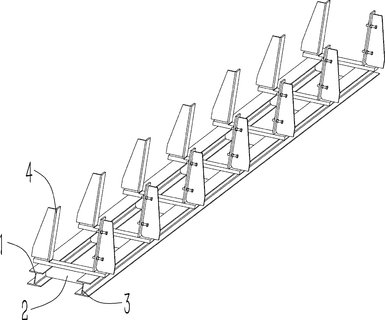
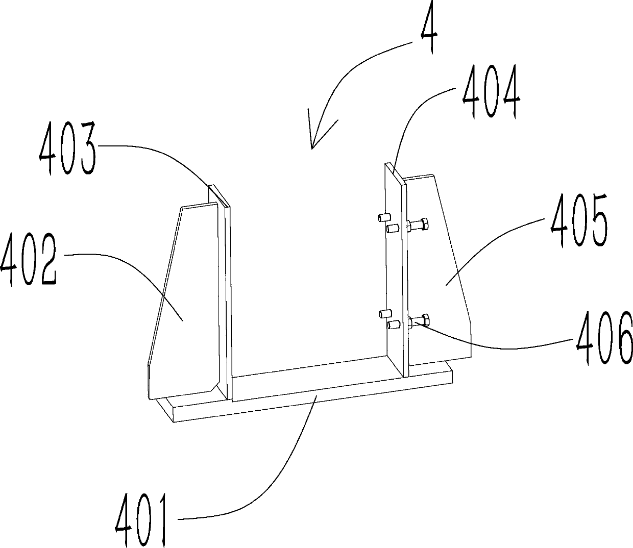
[0026] Such as Figure 1~4 As shown, a large-scale box girder welding platform includes a first I-beam 1 and a second I-beam 3 placed side by side, and a plurality of Connecting plate 2, the first I-beam 1 and the second I-beam 3 are connected through a plurality of connecting plates 2, a positioning device 4 is arranged above the connecting plate 2, and the large box beam is placed on the positioning device 4 The inside is fixed by bolts 406. With this structure, the platform base is connected by multiple connecting plates 2 between the first I-beam 1 and the second I-beam 3 to ensure the stability and levelness of the base itself, and place it on the base It is also necessary to ensure the levelness between the plurality of positioning devices 4, and the large box girder welded with the positioning device 4 as the reference can have higher verticality and levelness.

[0027] In a preferred solution, the horizontal plate 401 in the positioning device 4 is arranged above the ...

Embodiment 2

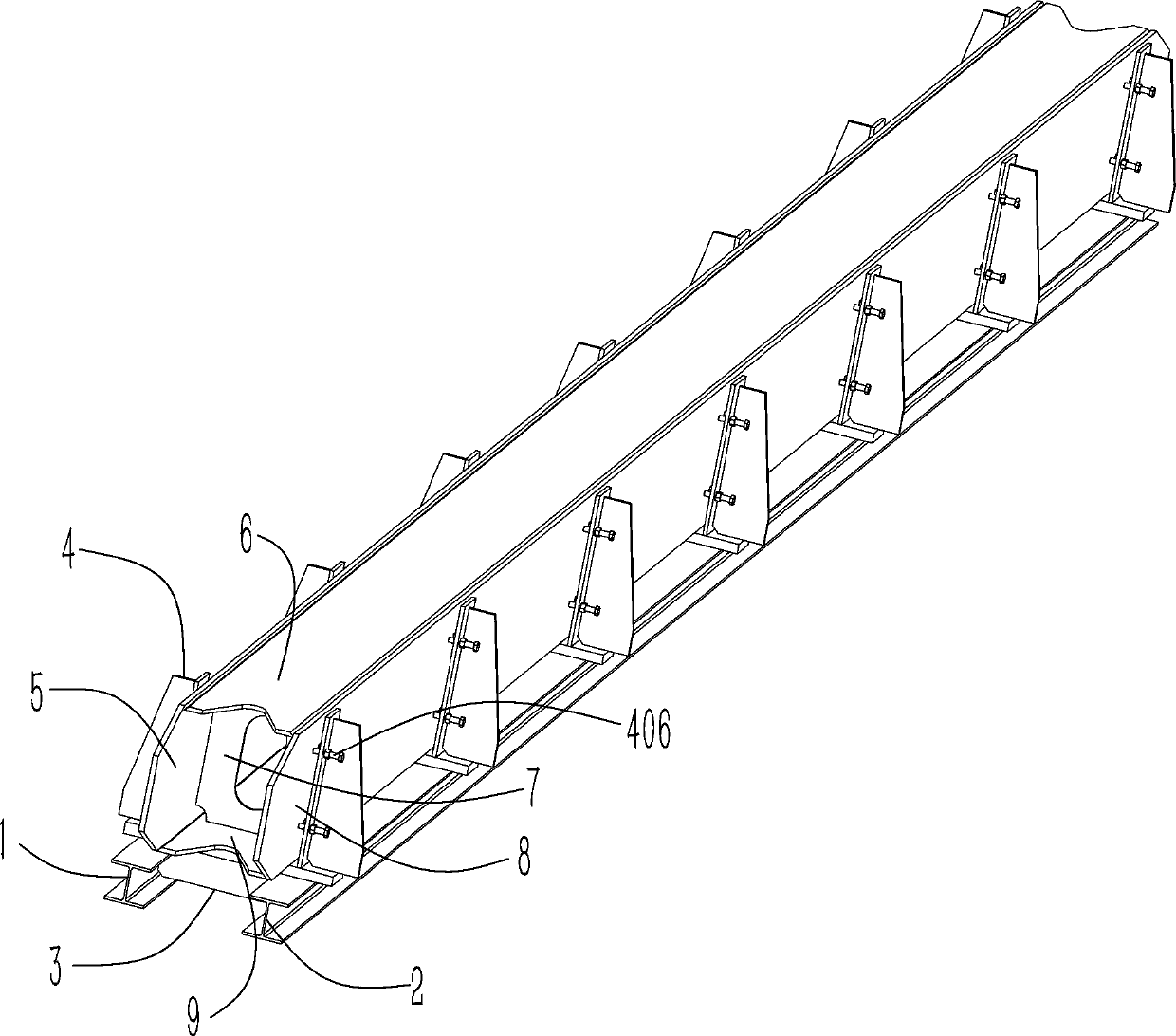
[0033] Further illustrate in conjunction with embodiment 1, as Figure 1~4 As shown, when the box girder is assembled and welded, the bottom plate 9 leans against the horizontal plate 401 and is fixed with a clamp; the left side plate 5 leans against the first vertical plate 403 and is fixed with a clamp; the left side plate 5 is welded with The abutment of the bottom plate 9; the two sides of a plurality of inner plates 7 are against the left side plate 5 and the bottom plate 9 for welding; the right side plate 8 is against the inner plate 7 and the bottom plate 9, and the adjustment bolt 406 is against the The right side plate 8 is pressed tightly; the right side plate 8 is welded on the inner plate 7 and the bottom plate 9; the top plate 6 is welded against the right side plate 8, the left side plate 5 and the inner plate 7; loosen the bolt 406 , Lift the large box girder that has been preliminarily welded to the submerged arc welding machine station for external full weldi...


PUM


Abstract

The invention provides a large box beam welding platform and a welding method. The large box beam welding platform comprises first I-shaped steel and second I-shaped steel which are placed in parallel, wherein a plurality of connecting plates are arranged between the first I-shaped steel and the second I-shaped steel; the first I-shaped steel and the second I-shaped steel are connected through theplurality of connecting plates; positioning devices are arranged above the connecting plates; a large box beam is placed in the positioning devices and is fixed through bolts; the plurality of positioning devices are uniformly arranged on the basis of the two I-shaped steel, so that the positioning devices are ensured to be positioned on the same horizontal plane; a first vertical plate and a second vertical plate in each positioning device are perpendicular to a transverse plate, so that the stability and the connectivity during welding are ensured; the large box beam is placed on the platform, so that the perpendicularity and the parallelism between the plates during welding can be ensured; the locking and the fixing are firm, the welding deformation is small, the tool positioning and clamping are achieved, and the size is welded in place in one step; and the flatness and the straightness of the welded beam are qualified in one-time acceptance, so that the large box beam welding platform is suitable for popularization and use.

Description

technical field [0001] The invention relates to the technical field of beam parts welding, in particular to a large box girder welding platform and a welding method. Background technique [0002] Large-scale beam parts are mainly used on steel bridges. The length of the parts is relatively long, basically more than 10 meters, and the requirements for flatness and straightness are extremely high. The current assembly and welding of such parts mainly adopts a large-scale welding platform, and the method of installing and welding parts by a square, the disadvantage is that the investment in equipment is high, it is difficult to control the size of large box girders, and the amount of deformation is unpredictable. The post-calibration workload is heavy, and the rework rate is high. Contents of the invention [0003] The main purpose of the present invention is to provide a large-scale box girder welding platform and welding method, which solves the problem of high equipment i...

Claims


Application Information

Patent Timeline
IPC IPC(8): B23K37/04B23K9/18
CPCB23K37/0443B23K9/18
Inventor 徐艳梅苏强高屹凯
Owner YICHANG JIANGXIA MARINE MACHINERY
Why Eureka
Try Eureka