Large I-shaped beam welding platform and welding method

A welding platform and I-beam technology, applied in welding equipment, welding equipment, auxiliary welding equipment, etc., can solve problems such as high investment, high rework rate, and unpredictable deformation

Pending Publication Date: 2020-03-24
YICHANG JIANGXIA MARINE MACHINERY
View PDF5 Cites 7 Cited by
  • Summary
  • Abstract
  • Description
  • Claims
  • Application Information

AI Technical Summary

Problems solved by technology

[0003] The main purpose of the present invention is to provide a large-scale I-beam welding platform and welding method, which solves the problem that the existing welding platform equipment investment is high, the size control of large-scale I-beams or H-beams is difficult to grasp, and the amount of deformation is unpredictable , the correction workload after welding is heavy, and the rework rate is high

Method used


Image

  • Large I-shaped beam welding platform and welding method
  • Large I-shaped beam welding platform and welding method
  • Large I-shaped beam welding platform and welding method

Examples


Embodiment 1

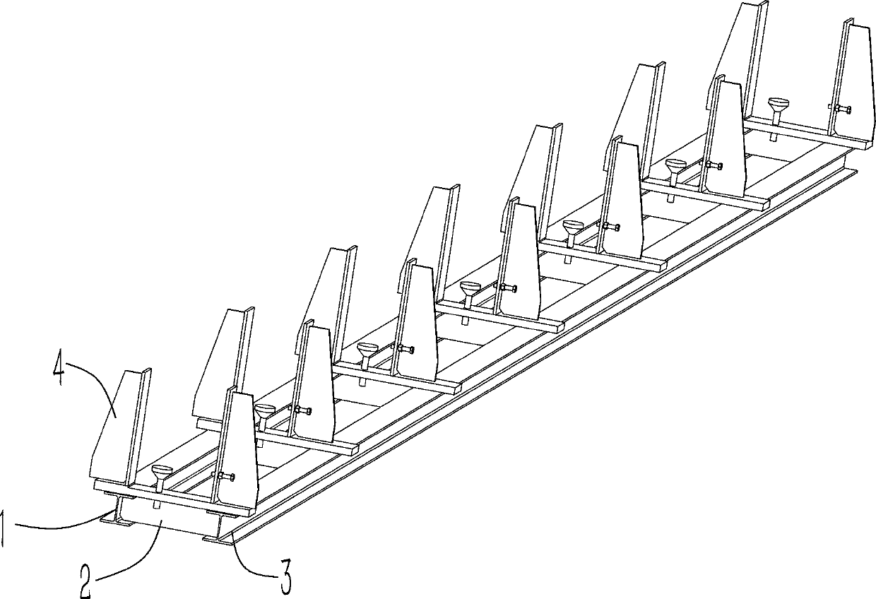
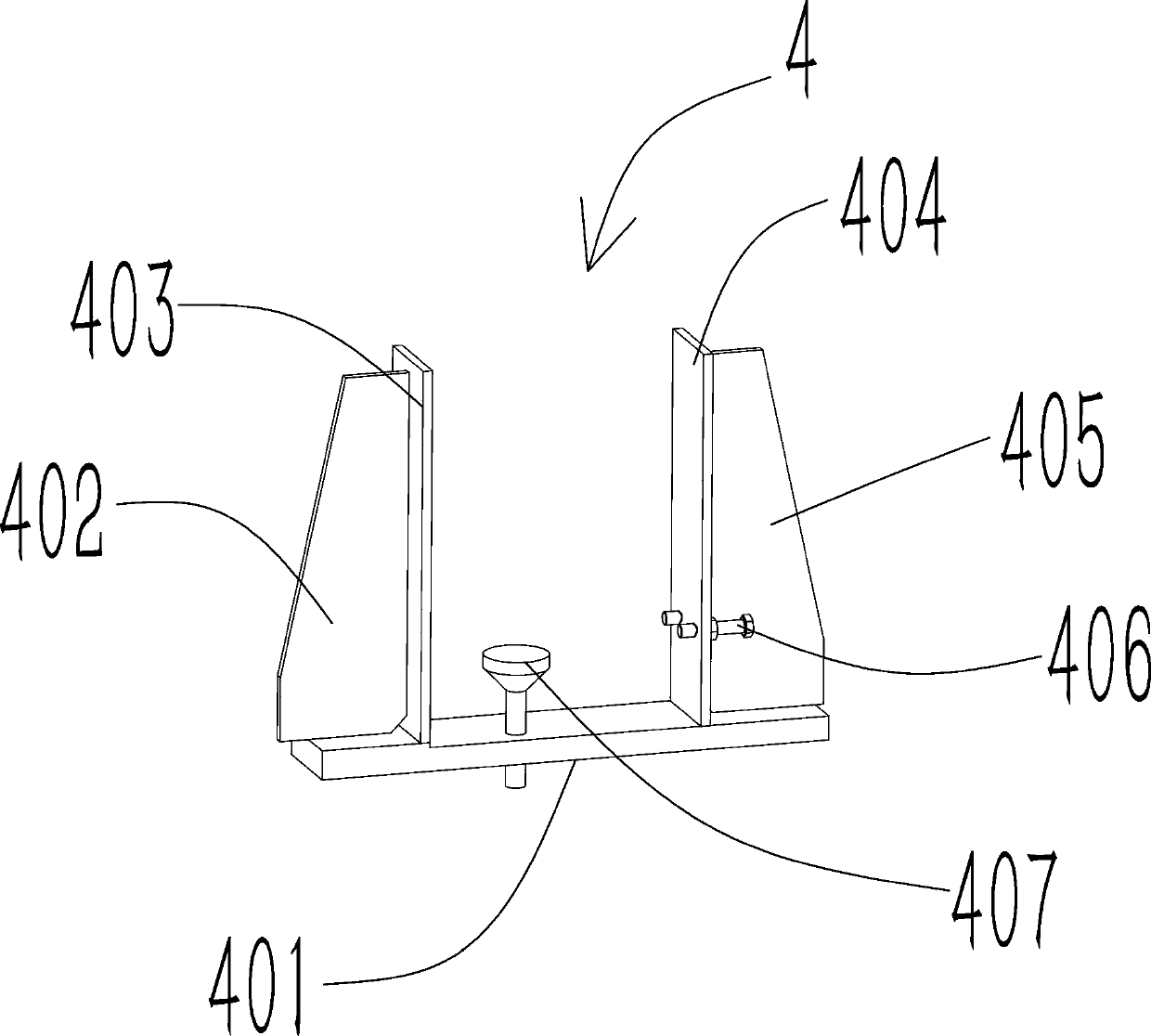
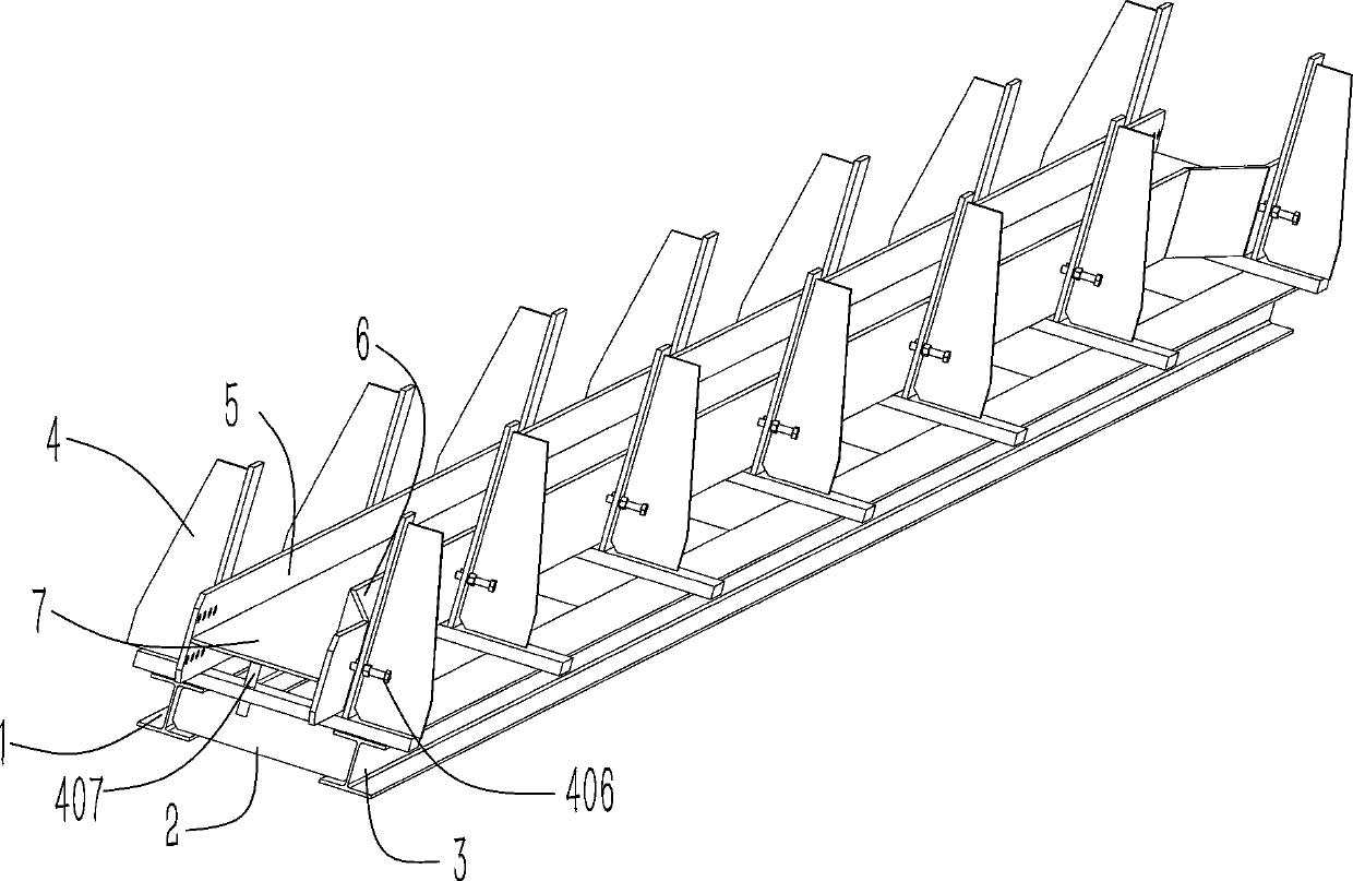
[0025] Such as Figure 1~4 As shown, a large-scale I-beam welding platform includes a first I-beam 1 and a second I-beam 3 placed side by side, and a plurality of Connecting plate 2, the first I-beam 1 and the second I-beam 3 are connected through a plurality of connecting plates 2, a positioning device 4 is provided above the connecting plate 2, and the large I-beam is placed on the positioning device In 4, the end face of the large I-beam is supported by pads 407, and the side of the large I-beam is locked and fixed by bolts 406. From this structure, the platform base is made of the first I-beam 1 and the second I-beam 3 Through the connection of multiple connecting plates 2, the stability and levelness of the base itself are guaranteed, and the levelness must also be ensured between multiple positioning devices 4 placed on the base. The large I-beam welded with the positioning device 4 as a reference can It has high verticality and horizontality.

[0026] In a preferred s...

Embodiment 2

[0033] Further illustrate in conjunction with embodiment 1, as Figure 1~4 As shown, when the I-beam is assembled and welded, the left side plate 5 leans against the first vertical plate 403; the height of the pad 407 is adjusted according to the welding height of the support plate 7; the support plate 7 is placed on the pad 407, One end of the support plate 7 leans against the left side plate 5; the right side plate 6 is leaned against the other end of the support plate 7, and the adjustment bolt 406 is pressed against the right side plate 6; the right side plate 6, the support plate 7 Weld the contact surface with the left side plate 5; loosen the bolt 406, hoist the large I-beam that has been initially welded to the submerged arc welding machine station for external full welding reinforcement, and the welding method of the H-beam and the I-beam is the same.


PUM


Abstract

The invention provides a large I-shaped beam welding platform and a welding method. The large I-shaped beam welding platform comprises first I-shaped steel and second I-shaped steel which are placed in parallel; multiple connecting plates are arranged between the first I-shaped steel and the second I-shaped steel; the first I-shaped steel and the second I-shaped steel are connected through the multiple connecting plates; positioning devices are arranged on the connecting plates respectively; a large I-shaped beam profile is placed in the positioning devices, the end surface of the large I-shaped beam profile is supported by cushion blocks, and the side surfaces of the large I-shaped beam profile are locked and fixed by bolts; all the positioning devices are ensured to be in one horizontalplane, a first vertical plate and a second vertical plate in each positioning device are perpendicular to a transverse plate, and the bolt on the second vertical plate are used for locking the right side plate of the large I-shaped beam; and by placing the large I-shaped beam on the platform, the perpendicularity and the parallelism between two plates during welding can be ensured, locking and fixing are firm, the welding deformation quantity is small, tool positioning and clamping are achieved, and mounting and welding in size are achieved into place with one step.

Description

technical field [0001] The invention relates to the technical field of beam parts welding, in particular to a large-scale I-beam welding platform and a welding method. Background technique [0002] Large-scale beam parts are mainly used on steel bridges. The length of the parts is relatively long, basically more than 10 meters, and the requirements for flatness and straightness are extremely high. The current assembly and welding of such parts mainly adopts a large-scale welding platform, and the method of installing and welding parts by squares, the disadvantage is that the investment in equipment is high, it is difficult to control the size of large I-beams or H-beams, and the amount of deformation Unpredictable, the calibration workload after welding is heavy, and the rework rate is high. Contents of the invention [0003] The main purpose of the present invention is to provide a large-scale I-beam welding platform and welding method, which solves the problem that the ...

Claims


Application Information

Patent Timeline
Patent Type & Authority Applications(China)
IPC IPC(8): B23K37/04B23K9/18
CPCB23K37/0443B23K9/18
Inventor 徐艳梅苏强高屹凯
Owner YICHANG JIANGXIA MARINE MACHINERY
Why Eureka
Try Eureka