
Nonlinear optical crystal laser frequency conversion coupler

A nonlinear crystal and nonlinear optics technology, applied in the field of optical couplers, can solve problems such as inability to change the incident angle, large light loss, errors, etc., to prevent temperature from affecting light conversion, simple and convenient operation, and prevent wavelength changes Effect

Active Publication Date: 2020-03-24
ANHUI UNIV OF SCI & TECH
View PDF8 Cites 1 Cited by
  • Summary
  • Abstract
  • Description
  • Claims
  • Application Information

AI Technical Summary

Problems solved by technology

[0005] When the frequency conversion coupler is used, the incident angle cannot be accurately changed. Usually, the incident angle of the light is changed by moving the light source or moving the coupler, but the accuracy of the incident angle of the moving light source or moving the coupler cannot be effectively determined. Then it is impossible to accurately calculate the exit angle and the wavelength of the exit light. At the same time, there are a lot of impurities in the optical glue and the triangular prism, and if the purity is insufficient, the exit angle and the exit angle of the exit light will change. In severe cases, the exit angle There is only one, and the light cannot be effectively distributed. At the same time, the OH- particles in the Sanjia prism and the optical glue have a large loss of light, and there are large errors in the calculation of the exit angle and the exit ray wavelength.

Method used


Image

  • Nonlinear optical crystal laser frequency conversion coupler
  • Nonlinear optical crystal laser frequency conversion coupler
  • Nonlinear optical crystal laser frequency conversion coupler

Examples


Embodiment approach

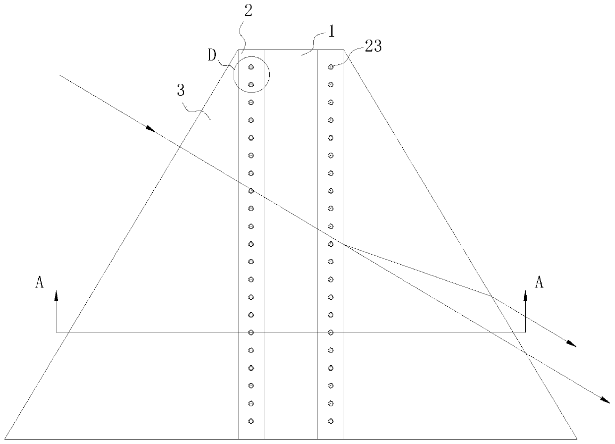
[0028] As an embodiment of the present invention, a matching liquid is housed in the cavity 21, and the matching liquid is high-purity distilled water; When working, by installing high-purity distilled water in the cavity 21 to prevent light from entering the cavity 21, the refractive index of the gas in the cavity 21 is different from that of the optical glue 2, causing light distortion and light loss, and there are more particles in the air , the light passes through the air to cause a large amount of scattering. After the magnification conversion, the wavelength of the outgoing rays decreases, which affects the accuracy of the magnification conversion and causes light energy loss.

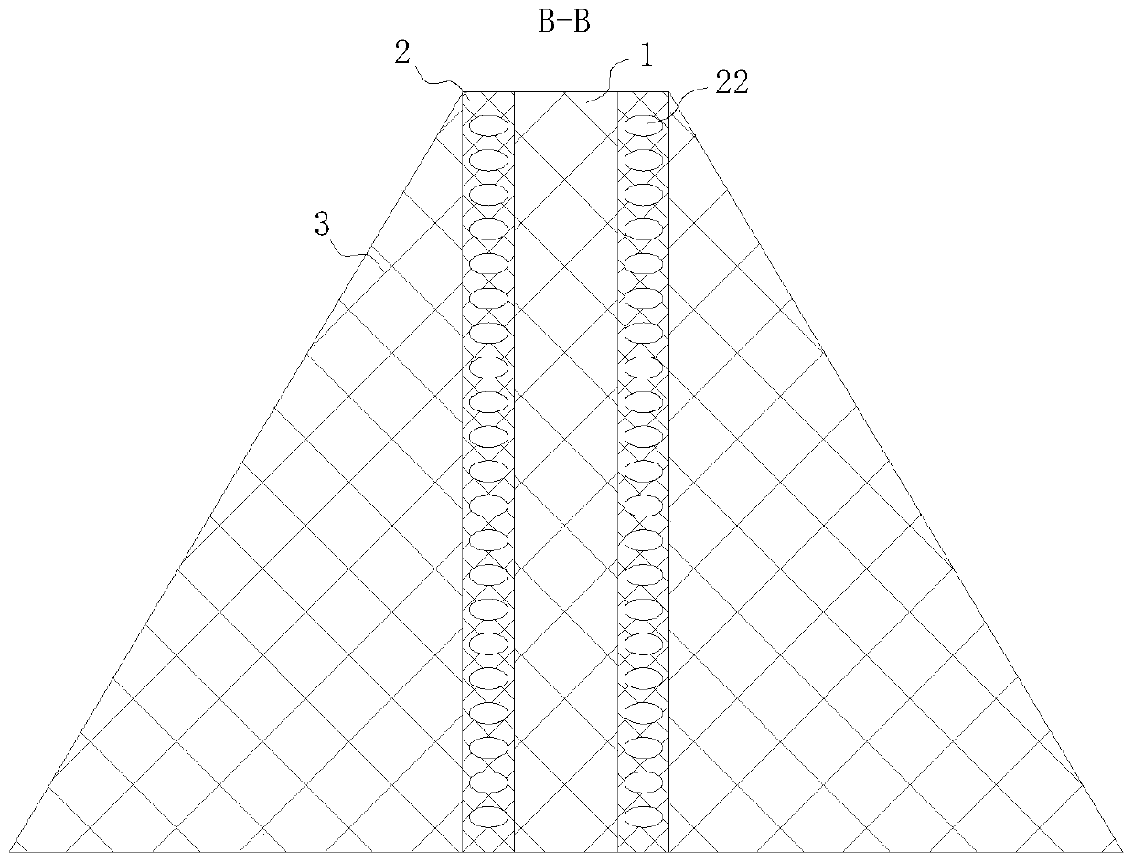
[0029] As an embodiment of the present invention, the expansion hole 22 has an elliptical design, and through the expansion hole 22, the wall thickness of the optical glue 2 close to the nonlinear crystal 1 and the triangular prism 3 is smaller than that of the optical glue 2 close to and away fr...


PUM


Abstract

The invention belongs to the technical field of optical couplers, and particularly relates to a nonlinear optical crystal laser frequency conversion coupler which comprises a nonlinear crystal. Triangular prisms are adhered to two sides of the nonlinear crystal through optical cement. The connection part between the triangular prism and the non-linear crystal is bonded through optical cement, so that the middle part between the triangular prism and the non-linear crystal is a hollow cavity. Expansion holes which are uniformly distributed are formed in the periphery of the optical cement. Injection ports in one-to-one correspondence with the expansion holes are formed in the surface of the optical cement. The expansion holes are designed to be oval. Uniformly-arranged plastic belts are arranged on the side, away from the cavity, of the expansion hole in the optical cement. According to the invention, the inclination angle of the triangular prism can be changed under the condition that the light position is not changed, so that the incident angle of the light is adjusted, and meanwhile, the influence on the precision of light multiplying power conversion due to a difference value ofmultiplying power conversion caused by incapability of realizing fine adjustment by manually moving the laser or coupler is avoided.

Description

technical field [0001] The invention belongs to the technical field of optical couplers, in particular to a nonlinear optical crystal laser frequency conversion coupler. Background technique [0002] In a microwave system, it is often necessary to divide the microwave power of one path into several paths in proportion, which is the problem of power allocation. The components that realize this function are called power distribution components, that is, couplers, and mainly include: directional couplers, power dividers, and various microwave branch devices. [0003] The well-known nonlinear optical crystal laser frequency conversion (including frequency doubling, sum frequency, difference frequency and optical parametric oscillation and amplification) is to cut the nonlinear optical crystal according to the phase-matching angle, and the frequency-converted laser is incident at a certain incident angle, and then rotated precisely The crystal adjusts the incident angle to the p...

Claims


Application Information

Patent Timeline
IPC IPC(8): H01S3/108G02F1/35
CPCG02F1/353H01S3/108
Inventor 李学超张粮成王平
Owner ANHUI UNIV OF SCI & TECH
Learn More