
Energy conversion device for inhibiting hydroelastic vibration of hull beam and design method thereof

A technology of energy conversion device and design method, which is applied in the direction of electromechanical devices, circuit devices, battery circuit devices, etc., and can solve the time-consuming and laborious deployment, installation, transportation and maintenance of large wave energy conversion devices, and limit the development and promotion of small wave energy conversion devices to generate electricity Improve efficiency, increase use cost and other issues, achieve the effect of suppressing hydroelastic vibration, reducing damage and destruction, and reducing dissipation loss

Inactive Publication Date: 2020-03-24
SOUTH CHINA UNIV OF TECH
View PDF10 Cites 2 Cited by
  • Summary
  • Abstract
  • Description
  • Claims
  • Application Information

AI Technical Summary

Problems solved by technology

This limits the development and promotion of small-scale wave energy conversion devices and the improvement of power generation efficiency
[0007] (3) Conventional large-scale wave energy conversion devices generally need to be deployed in deep seas. The deployment, installation, transportation and maintenance of large-scale wave energy conversion devices are time-consuming and laborious. moor
In addition, the electric energy generated by the wave energy conversion device needs to be transmitted to the shore with a long cable, which also greatly increases the cost of use

Method used


Image

  • Energy conversion device for inhibiting hydroelastic vibration of hull beam and design method thereof
  • Energy conversion device for inhibiting hydroelastic vibration of hull beam and design method thereof
  • Energy conversion device for inhibiting hydroelastic vibration of hull beam and design method thereof

Examples


Embodiment Construction

[0032] The present invention will be further described in detail below in conjunction with the embodiments and the accompanying drawings, but the embodiments of the present invention are not limited thereto.

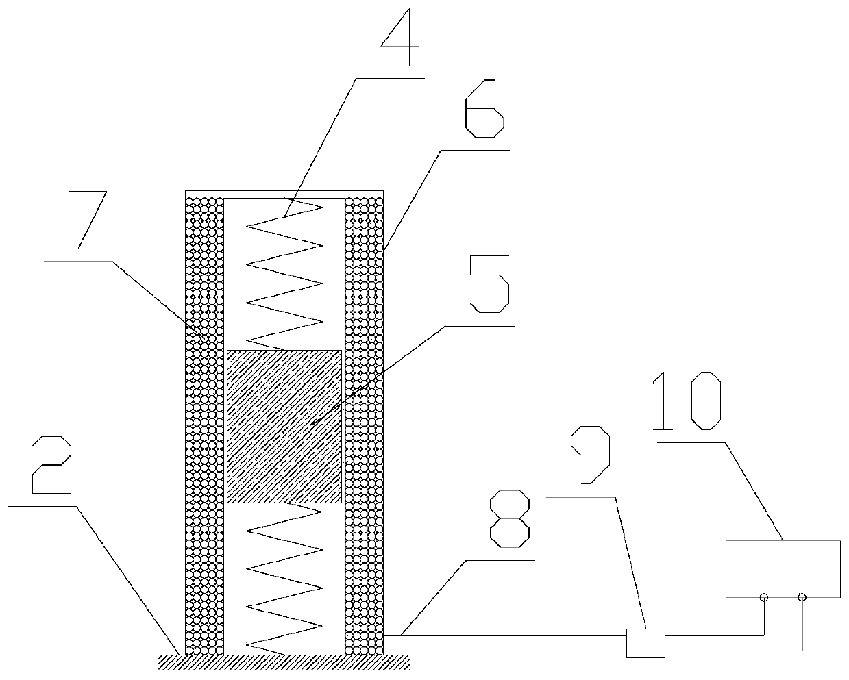
[0033] Such as figure 1As shown, an energy conversion device for suppressing the hydroelastic vibration of the hull girder includes a stator, a vibrator, a spring, a cable, a rectifying device and a storage battery. The stator consists of a sleeve and painted copper coils. Both ends of the vibrator are respectively connected with one ends of two springs, and placed in the inner cavity defined by the stator sleeve, and the other ends of the two springs are respectively fixed with the upper and lower walls of the sleeve. The vibrator is a cylindrical permanent magnet, and its surface is coated with lubricating oil, which can reduce the energy loss caused by friction with the sleeve during the vibration process. The painted copper coil is wound on the outer wall of the sl...


PUM


Abstract

The invention discloses an energy conversion device for inhibiting hydroelastic vibration of a hull beam and a design method of the energy conversion device. The device comprises a stator, a vibrator,springs, a cable, a rectifying device and a storage battery, the stator comprises a sleeve and a coil, the two ends of the vibrator are connected with one ends of the two springs respectively and placed in an internal cavity defined by the stator sleeve, and the other ends of the two springs are fixed to the upper wall face and the lower wall face of the sleeve respectively; the coil is wound onthe outer wall surface of the sleeve; the coil is electrically connected with the rectifying device and the storage battery in sequence through cables; the energy conversion device is installed on thehull, and the inherent frequency of the energy conversion device is equal to that of hull beam vibration. The inherent frequency of the energy conversion device is designed to be the inherent frequency of vibration of the ship body beam, structural damage caused by vibration of the ship body can be effectively relieved, energy in vibration of the ship body can be efficiently captured through theresonance phenomenon, and therefore wave energy is indirectly converted into electric energy to be used by electronic equipment on a ship. The invention relates to the technical field of ship vibration.

Description

technical field [0001] The invention relates to the technical field of ship vibration, in particular to an energy conversion device for suppressing hydroelastic vibration of a hull girder and a design method thereof. Background technique [0002] With the continuous development of the global economy and the recovery of the international shipping industry, modern ships are moving towards large-scale, high-speed and lightweight trends, which makes the natural frequency of hull girder vibration gradually decrease and tends to encounter frequency under normal sea conditions, resulting in The hydroelastic effect of the hull structure becomes more and more obvious. When a ship sails in waves, two modes of hull girder vibration will occur: one is the hull girder flutter response induced by the severe slamming phenomenon between the bow and stern of the ship and the waves under high sea conditions, and the flutter load in the structure Damping rapidly attenuates, but the huge insta...

Claims


Application Information

Patent Timeline
Patent Type & Authority Applications(China)
IPC IPC(8): H02K35/02H02J7/32
CPCH02J7/32H02K35/02
Inventor 焦甲龙陈超核黄松兴
Owner SOUTH CHINA UNIV OF TECH
Learn More