Gypsum cutting device for orthopedic treatment

A cutting device and gypsum technology, applied in medical science, stone processing tools, stone processing equipment, etc., can solve problems such as movement, cutting knife contact, skin injury, etc., and achieve the effect of reducing the probability of rotation and tight adsorption

Active Publication Date: 2020-03-27
THE FIRST AFFILIATED HOSPITAL OF ARMY MEDICAL UNIV
View PDF12 Cites 4 Cited by
  • Summary
  • Abstract
  • Description
  • Claims
  • Application Information

AI Technical Summary

Problems solved by technology

[0003] The present invention intends to provide a gypsum cutting device for orthopedic treatment to solve the problem that when cutting gypsum in the prior art, the patient will move due to mental stress and stress response, and then come into contact with the cutting knife, resulting in skin injury problem

Method used


Image

  • Gypsum cutting device for orthopedic treatment
  • Gypsum cutting device for orthopedic treatment
  • Gypsum cutting device for orthopedic treatment

Examples


Embodiment 1

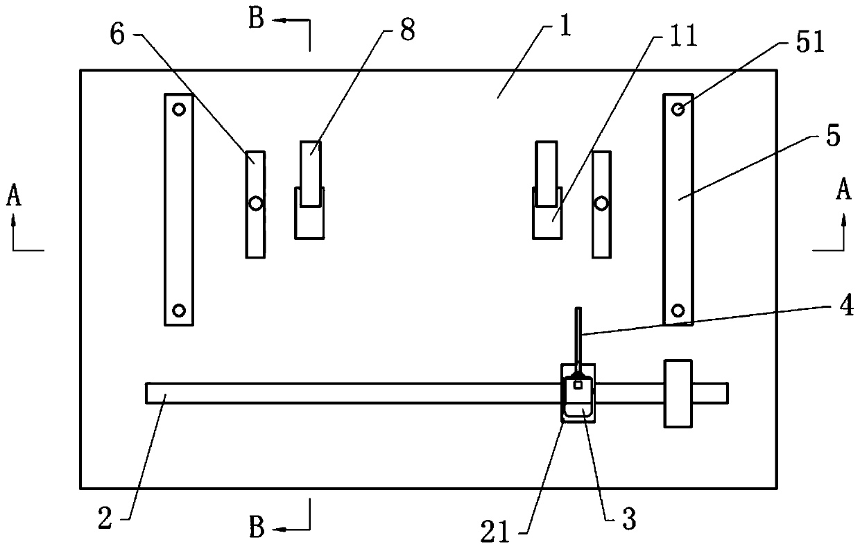
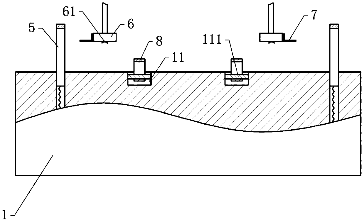
[0036] A plaster cutting device for orthopedic treatment, basically as attached figure 1 , figure 2 As shown, it includes workbench 1, which is provided with a horizontal chute, and a ball screw 2 is arranged in the chute, and a slider 21 is fixed on the ball screw 2. When the ball screw 2 starts, it can realize The slider 21 slides reciprocally laterally. The upper surface of the slide block 21 is provided with a vertical groove (i.e. a groove perpendicular to the chute), and a motor 3 is slidably connected in the vertical groove, and the output shaft of the motor 3 is provided with a cutting knife 4. The slider 21 is also fixed with an infrared detector and a controller that controls the sliding of the cutting knife 4 along the slider 21. The infrared detector can detect the thickness of the plaster and transmit the signal to the controller, so that the controller controls the sliding of the cutting knife 4 , realizing the real-time adjustment of the position of the cutti...

Embodiment 2

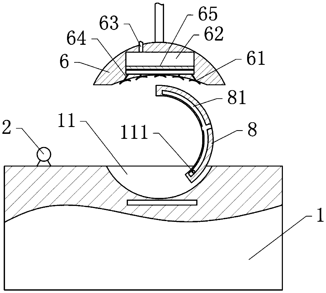
[0046] The difference between embodiment 2 and embodiment 1 is only that, as Figure 4 , Figure 5 As shown, the left end of the arc-shaped block 8 is provided with an arc-shaped hole 82 concentric with it, and an arc-shaped sliding block 83 is slidably connected in the arc-shaped hole 82, and the opening end of the arc-shaped hole 82 in the sliding block 83 is provided with a limit block 84 One end of the sliding block 83 located in the arc-shaped hole 82 is provided with a protrusion 85 . The pressing block 6 is located above the arc block 8 .

[0047] The specific implementation process is as follows: when the arc block 8 is fixed, the slide block 83 is partly slid out of the arc hole 82, and when the pressing block 6 moves down, it contacts with the slide block 83. The surface should be smooth, so that the suction cup 61 can be fixed more tightly. After the gypsum is cut twice, the separation effect is better, and the compression effect is also better.


PUM


Abstract

The invention belongs to the technical field of medical instruments for cutting various bandages, and discloses a gypsum cutting device for orthopedic treatment. The device comprises a workbench, a sliding groove is formed in the workbench, a cutting knife driven by a motor is connected to the sliding groove in a sliding mode, the device further comprises a sliding block connected into the slidinggroove in a sliding mode, the cutting knife is connected to the sliding block in a sliding mode in a direction perpendicular to the sliding groove, and an infrared detector and a controller controlling the cutting knife to slide are arranged on the sliding block; and a gypsum containing groove is further formed on the workbench, two sets of sliding holes are further formed in the positions, located on the two sides of the gypsum containing groove, of the upper surface of the workbench, two human body fixing rings sliding along the sliding holes are further included, threaded mounting holes are formed on the human body fixing rings, and threaded locking holes are formed in the positions, located below the mounting holes, of the workbench. The invention solves the problems that: in the prior art, when gypsum is cut, a patient moves due to mental stress and stress reaction and then makes contact with a cutting knife, and consequently the skin is injured.

Description

technical field [0001] The invention belongs to the technical field of medical equipment for cutting various types of bandages, and in particular relates to a plaster cutting device for orthopedic treatment. Background technique [0002] In orthopedic treatment, in order to fix the affected part of the patient and promote the normal healing of the bones, it is usually necessary to put plaster on the affected part of the patient to keep the limbs fixed. After the patient's affected area has healed, the cast will need to be removed. The traditional method is to use a manual cutter to cut out the gap in the plaster, and then break the plaster into pieces. In this method, the operator controls the cutting depth. If the control is not good, the patient's skin may be injured. Therefore, a kind of plaster cutting device has occurred, which can keep the cutting knife stable and reduce the situation of cutting the patient's skin. But when cutting, because the patient is in a state ...

Claims


Application Information

Patent Timeline
Patent Type & Authority Applications(China)
IPC IPC(8): A61F15/02B28D1/22
CPCA61F15/02B28D1/22
Inventor 杨森罗飞杜诗宇陈玥琦汤勇陈灿李凯
Owner THE FIRST AFFILIATED HOSPITAL OF ARMY MEDICAL UNIV
Why Eureka
Try Eureka