Tractor
A tractor and tractor technology, applied in the tractor field, can solve the problems of noise and little effect, and achieve the effects of reducing disease incidence, preventing scratches of the pliers and knife group, and having a significant noise reduction effect.
- Summary
- Abstract
- Description
- Claims
- Application Information
AI Technical Summary
Problems solved by technology
Method used
Image
Examples
Embodiment 1
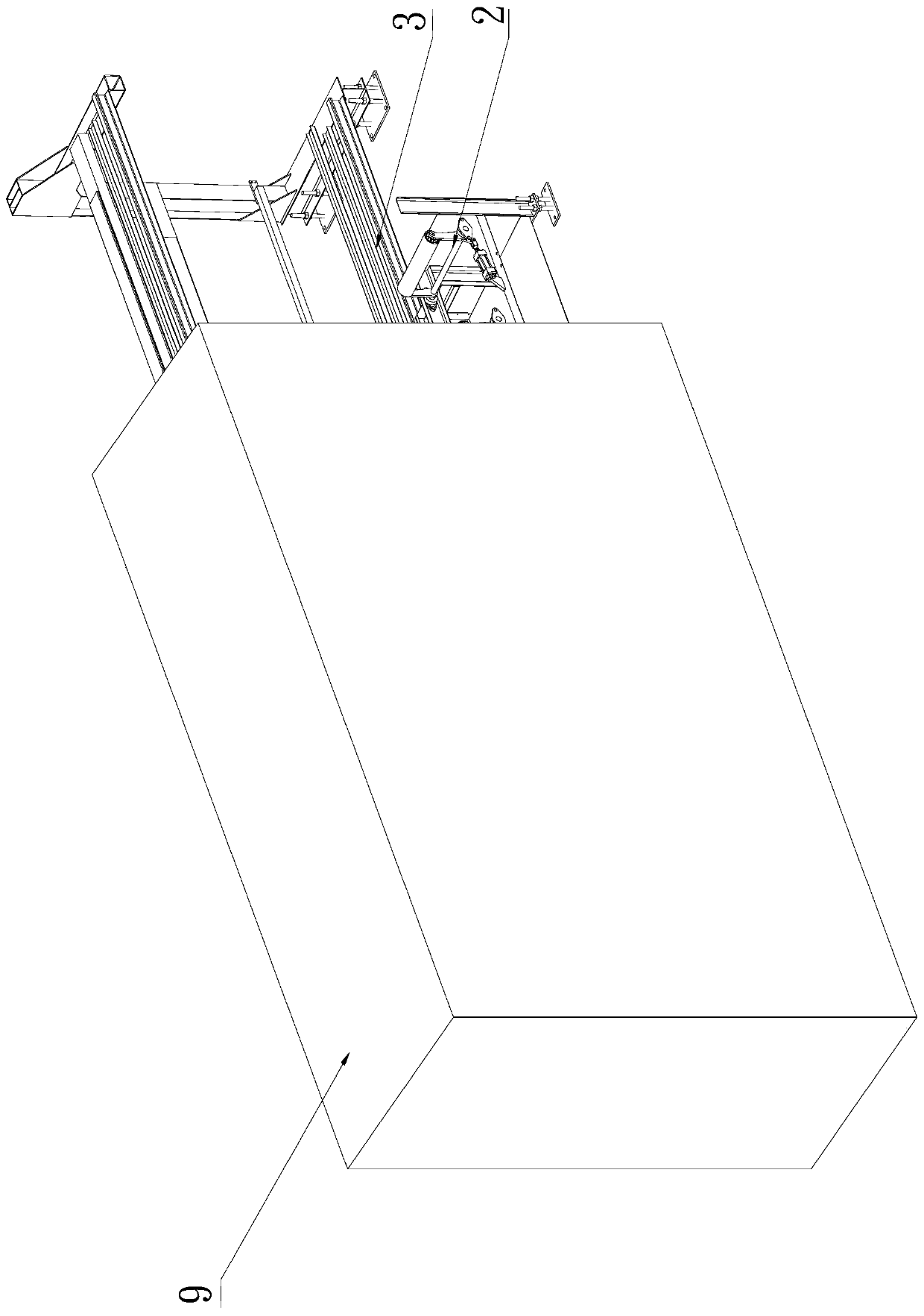
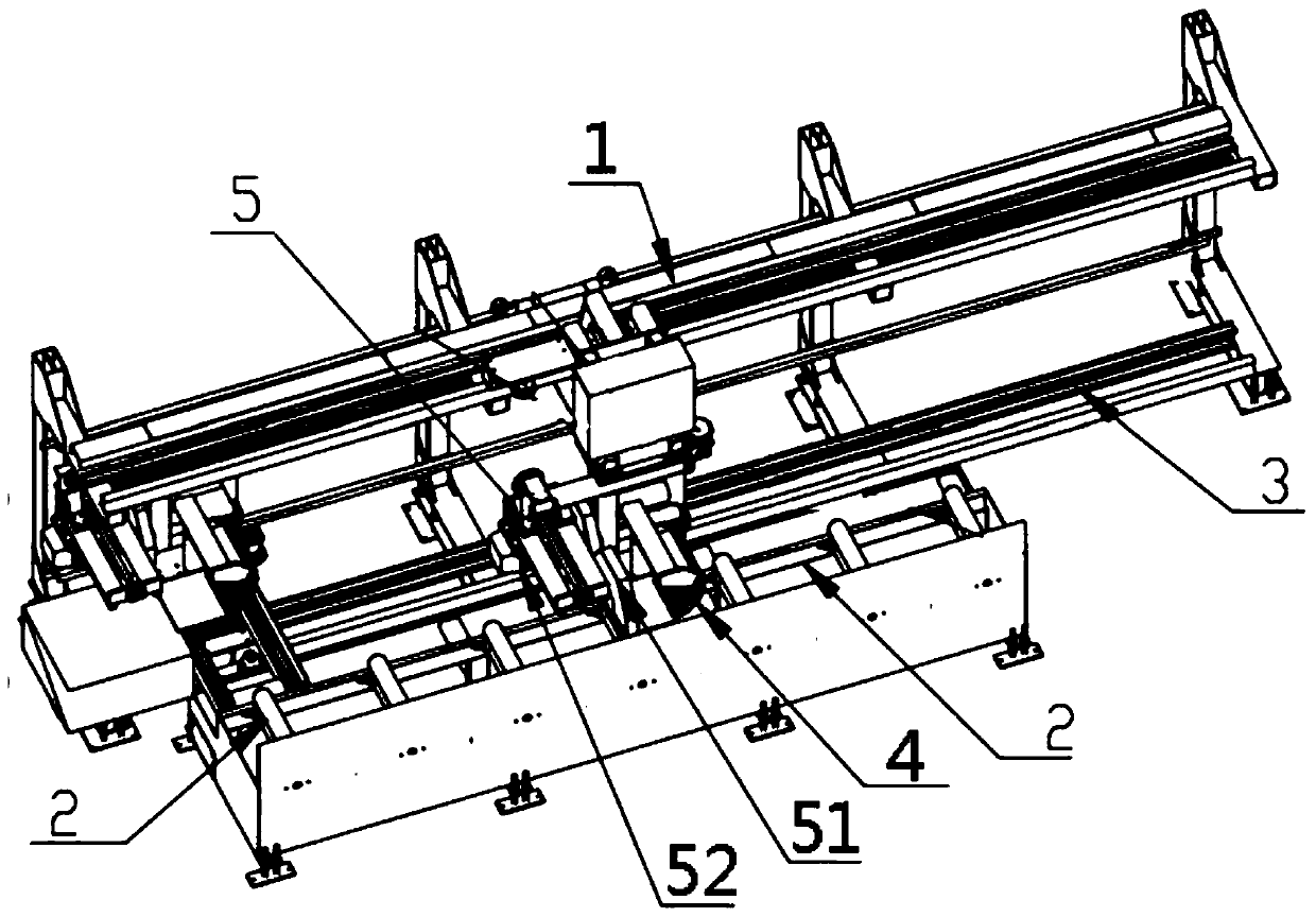
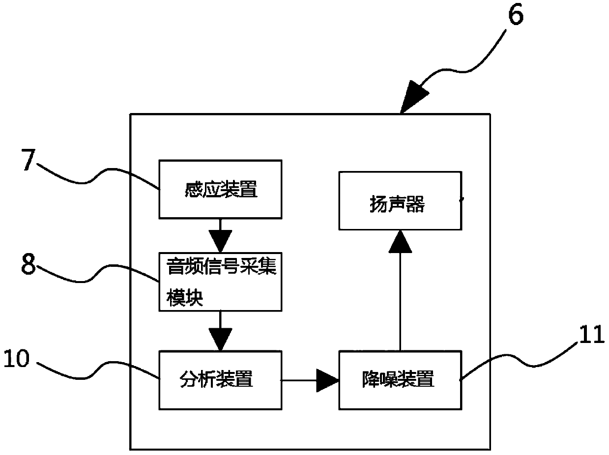
[0028] like Figure 1~3 A kind of pulling machine shown, it comprises frame 1 and is located at the conveying device 2 on described frame 1; Described frame 1 is also provided with traction guide rail 3; Described traction guide rail 3 is positioned at described conveying device Near 2; the traction guide rail 3 is provided with a traction device 4 reciprocating along its guiding direction; the conveying device 2 is provided with a cutting device 5 for cutting profiles; the traction device 5 is located at the cutting device 5 Lower station; the cutting device 5 includes a sawtooth block 51 and a drive motor 52 that controls the running state of the sawtooth block 51; the frame 1 is also provided with a soundproof cover arranged along the direction of the traction guide rail 3 9; the soundproof cover 9 is provided with a cavity; one end side of the soundproof cover 9 is provided with an opening communicating with the cavity; the delivery device 2 and the cutting device 4 are bo...
Embodiment 2
[0036] like Figure 1~3 A kind of pulling machine shown, it comprises frame 1 and is located at the conveying device 2 on described frame 1; Described frame 1 is also provided with traction guide rail 3; Described traction guide rail 3 is positioned at described conveying device Near 2; the traction guide rail 3 is provided with a traction device 4 reciprocating along its guiding direction; the conveying device 2 is provided with a cutting device 5 for cutting profiles; the traction device 5 is located at the cutting device 5 Lower station; the cutting device 5 includes a sawtooth block 51 and a drive motor 52 that controls the running state of the sawtooth block 51; the frame 1 is also provided with a soundproof cover arranged along the direction of the traction guide rail 3 9; the soundproof cover 9 is provided with a cavity; one end side of the soundproof cover 9 is provided with an opening communicating with the cavity; the delivery device 2 and the cutting device 4 are bo...
Embodiment 3
[0046] In Embodiment 3, on the basis of Embodiment 1 and Embodiment 2, in order to improve its automation level, improve work efficiency, and reduce human labor, a control system for controlling the cutting device is also provided, including and three modes of control parameters parameter optimization controller, main motion control loop, feed motion control loop, saw blade vibration elimination loop, sawing error compensation loop and photoelectric broken tooth detection device; among them, the three mode parameter optimization controllers Output the optimized parameter value to the main motion control loop, the feed motion control loop, the saw blade vibration elimination loop and the sawing error compensation loop; The speed value is output to the main motion controller, and the main motion controller controls the speed of the sawtooth block 51 by controlling the main motion servo motor; Input to the feed motion controller, the feed motion controller controls the speed of t...
PUM
 Abstract
Description
Claims
Application Information
 - R&D
- Intellectual Property
- Life Sciences
- Materials
- Tech Scout
- Unparalleled Data Quality
- Higher Quality Content
- 60% Fewer Hallucinations
Browse by: Latest US Patents, China's latest patents, Technical Efficacy Thesaurus, Application Domain, Technology Topic, Popular Technical Reports.
© 2025 PatSnap. All rights reserved.Legal|Privacy policy|Modern Slavery Act Transparency Statement|Sitemap|About US| Contact US: help@patsnap.com


