Automatic welding equipment realizing automatic tin feeding

An automatic equipment, tin welding technology, applied in welding equipment, metal processing equipment, tin feeding devices, etc., can solve the problems of manual soldering operation time can not be guaranteed consistent, affect product welding quality, welding quality depends on other problems, to improve welding quality , to ensure consistency, to ensure the effect of accuracy

Active Publication Date: 2020-03-27
CHANGDE FUBO INTELLIGENCE TECH CO LTD
View PDF23 Cites 0 Cited by
  • Summary
  • Abstract
  • Description
  • Claims
  • Application Information

AI Technical Summary

Problems solved by technology

[0005] Aiming at the deficiencies of the prior art, the present invention provides an automatic tin-adding and welding automatic equipment, which solves the problem that the prior art is widely used in manual soldering. During the welding process of manual soldering, its welding speed, tin feeding amount, welding time, etc. are affected. Human factors are greatly affected, and the quality of welding depends on the experience of workers. It only plays a certain role in small enterprises, and the scope and effect of solving the problem are too small, and the manual soldering operation time cannot be guaranteed to be consistent, which affects the welding quality of the product.

Method used


Image

  • Automatic welding equipment realizing automatic tin feeding
  • Automatic welding equipment realizing automatic tin feeding
  • Automatic welding equipment realizing automatic tin feeding

Examples


Embodiment 1

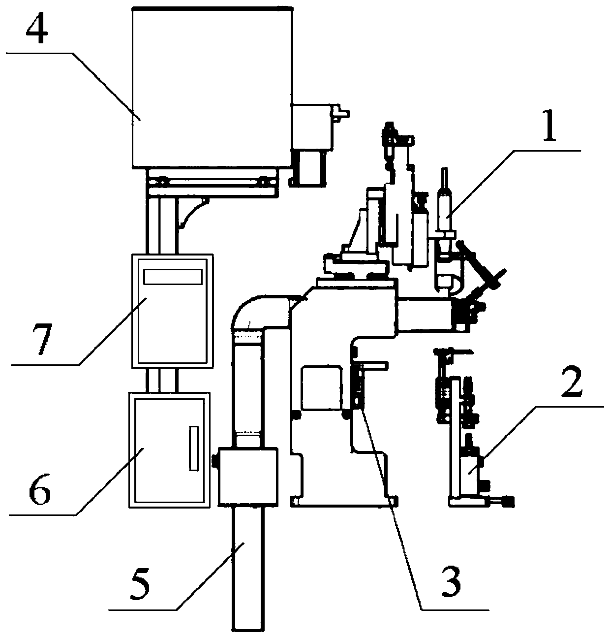
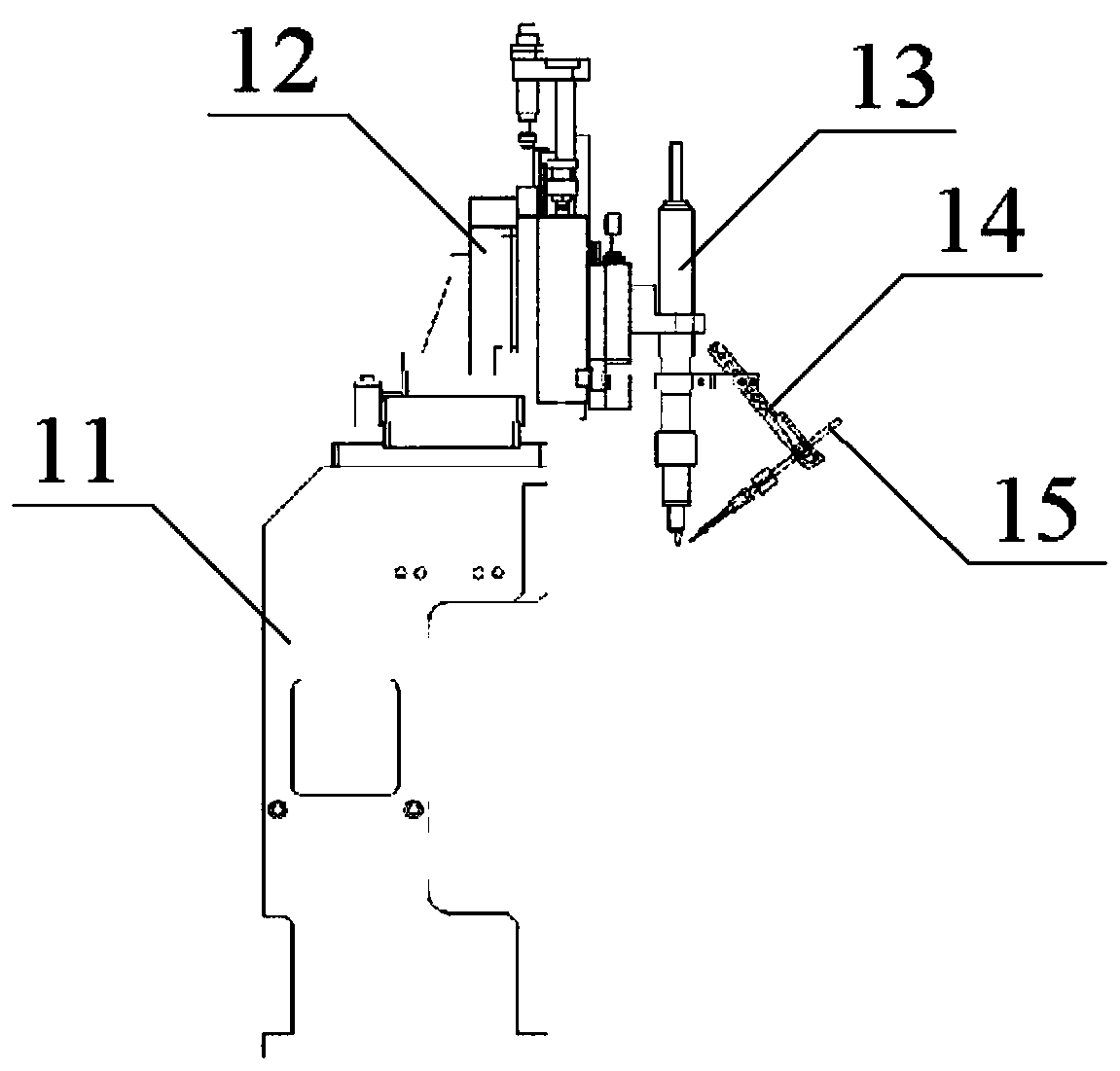
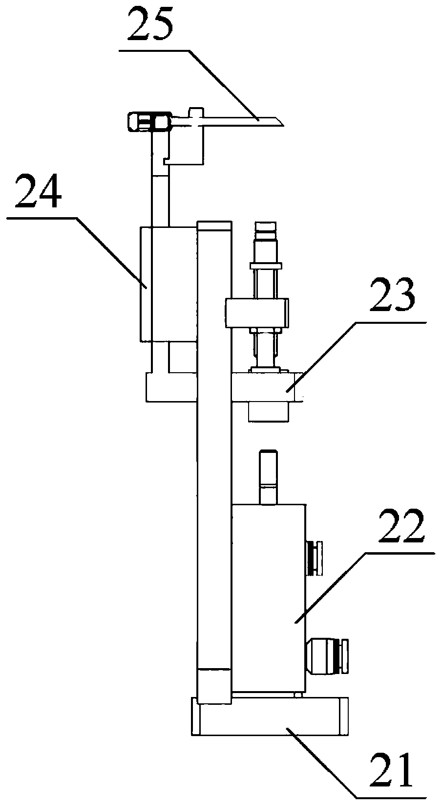
[0027] Such as Figure 1-6 As shown, the present invention provides a technical solution: an automatic tinning welding equipment, including a welding assembly, a product positioning assembly, a fixture positioning assembly, an automatic tinning assembly, a waste gas treatment assembly, an electric control cabinet and a PLC controller. The product positioning assembly is fixed below the right side of the welding assembly by bolts; the clamp positioning assembly is fixed below the inner side of the welding assembly by bolts, and the clamp positioning assembly is located on the left side of the product positioning assembly; the exhaust gas treatment assembly It is fixed on the left side of the welding assembly by bolts; the automatic tinning assembly is fixed on the left side of the exhaust gas treatment assembly by bolts; the PLC controller is fixed on the bottom of the front side of the automatic tinning assembly by bolts, and the PLC control The device is connected to the elec...

Embodiment 2

[0029] An automatic tinning and welding automatic equipment, including a welding assembly, a product positioning assembly, a fixture positioning assembly, an automatic tinning assembly, an exhaust gas treatment assembly, an electric control cabinet and a PLC controller, and the product positioning assembly is fixed on the welding assembly by bolts the bottom of the right side; the fixture positioning component is fixed on the bottom of the inner side of the welding component by bolts, and the fixture positioning component is located on the left side of the product positioning component; the exhaust gas treatment component is fixed on the left side of the welding component by bolts; the The automatic tinning assembly described above is fixed on the left side of the exhaust gas treatment assembly by bolts; the PLC controller is fixed below the front side of the automatic tinning assembly by bolts, and the PLC controller is connected to the electric control cabinet through wires; ...

Embodiment 3

[0033]An automatic tinning and welding automatic equipment, including a welding assembly, a product positioning assembly, a fixture positioning assembly, an automatic tinning assembly, an exhaust gas treatment assembly, an electric control cabinet and a PLC controller, and the product positioning assembly is fixed on the welding assembly by bolts the bottom of the right side; the fixture positioning component is fixed on the bottom of the inner side of the welding component by bolts, and the fixture positioning component is located on the left side of the product positioning component; the exhaust gas treatment component is fixed on the left side of the welding component by bolts; the The automatic tinning assembly described above is fixed on the left side of the exhaust gas treatment assembly by bolts; the PLC controller is fixed below the front side of the automatic tinning assembly by bolts, and the PLC controller is connected to the electric control cabinet through wires; T...


PUM


Abstract

The invention discloses an automatic welding equipment realizing automatic tin feeding. The automatic welding equipment comprises a welding component, a product positioning component, a clamp positioning component, an automatic tin feeding component, a waste gas processing component, an electric control cabinet and a PLC. According to the automatic welding equipment disclosed by the invention, theautomatic tin feeding component and the welding component are arranged; the PLC is used for controlling a wire sending motor and a welding handle to act; the wire conveying motor is used for sendinga wire disc positioned on a wire disc rod into a tin feeding pipe via a wire discharging opening so as to realize the aims of automatic wire conveying and automatic welding; compared with a method adopting manual tin welding, the automatic welding equipment disclosed by the invention is more varied in welding function; to spot welding, the use amount can be saved by 15% based on manual welding; the waste gas processing component is arranged and an air exhaust fan is powered on to run in a welding process so as to convey waste gas generated in the welding process into a purifier, and then the waste gas is discharged after being purified, thus the aim of purification of the waste gas is realized; and harms caused by the waste gas to the body health of an operator are prevented.

Description

technical field [0001] The invention relates to the technical field of welding equipment, in particular to an automatic tinning welding equipment. Background technique [0002] At present, artificial soldering is commonly used in the soldering process of the electronics industry. As we all know, the flux in the tin wire will have a huge impact on the human body and the surrounding environment. With the development of the modern automation industry, people's awareness is increasing. Protecting the natural environment, reducing industrial pollution, improving efficiency, and improving quality have become more and more popular. People are concerned that in order to eliminate the harm of flux to the human body and improve production efficiency, it is necessary to adopt the advantages of automatic soldering machines. Therefore, it is urgent to develop an automatic tinning and welding automatic equipment to solve the above problems and facilitate market promotion and application. ...

Claims


Application Information

Patent Timeline
Patent Type & Authority Applications(China)
IPC IPC(8): B23K3/06B23K3/08B23K3/00
CPCB23K3/06B23K3/08B23K3/00B23K3/063B23K3/0607B23K3/087
Inventor 王雯静张渊黄山松谢来华杨鲁黄晶成文锋蒋国锋陶咏平张国卿
Owner CHANGDE FUBO INTELLIGENCE TECH CO LTD
Why Eureka
Try Eureka