Production process for oil tank

A production process and oil tank technology, applied in metal material coating process, fixed filter element filter, filtration separation, etc., can solve the problems of lowering the product quality of the oil tank, not cleaning the surface of the oil tank very thoroughly, affecting the quality of spray painting, etc., to achieve improvement The quality and effect of pickling, the realization of cleaning and automatic collection, and the effect of improving cleaning efficiency

Active Publication Date: 2020-03-27
杭州樱多电器有限公司
View PDF8 Cites 3 Cited by
  • Summary
  • Abstract
  • Description
  • Claims
  • Application Information

AI Technical Summary

Problems solved by technology

[0004] After the above-mentioned fuel tank is processed and shaped, it is usually necessary to clean and paint the fuel tank. However, when cleaning, usually only the impurities on the surface of the fuel tank are initially cleaned. The product quality after production of the fuel tank has been reduced, which needs to be improved

Method used


Image

  • Production process for oil tank
  • Production process for oil tank
  • Production process for oil tank

Examples


Embodiment 1

[0053] Embodiment 1: a kind of production technology for oil tank, comprises the following steps:

[0054] S1, cutting the plate, cutting the plate according to the actual size requirement of the fuel tank, and making the cut plate larger than the actual size requirement of the fuel tank.

[0055] S2, stamping, stamping the cut plate to form the prototype of half a fuel tank.

[0056] S3, edge trimming, cutting the corners around the stamped plate.

[0057] S4, punching, punching the punched plate to form the fuel tank port.

[0058] S5, welding, fasten a pair of preliminarily formed fuel tanks together, and weld the joints of the two, and weld the corner ears and oil pipes at the same time.

[0059] S6, air-tightness test, immersing the formed fuel tank in clear water, observing whether there are bubbles in the clear water, so as to judge the air-tightness of the fuel tank.

[0060] S7, cleaning, cleaning the surface of the oil tank.

[0061] S8, plastic spraying, spray p...

Embodiment 2

[0069] Embodiment 2: Steps S71, S72, S73 and S74 are all performed in cleaning equipment.

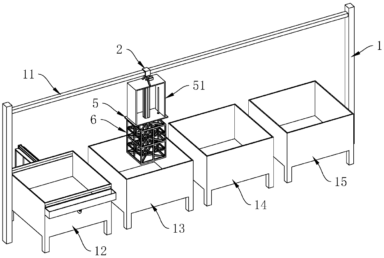
[0070] Such as figure 1 As shown, the cleaning equipment includes a pair of vertical columns 1, a beam 11 is horizontally arranged between the upper ends of the pair of columns 1, and a pickling pool 12, a neutralization pool 13, and a phosphating pool are sequentially arranged below the beam 11 14 and washing pool 15.

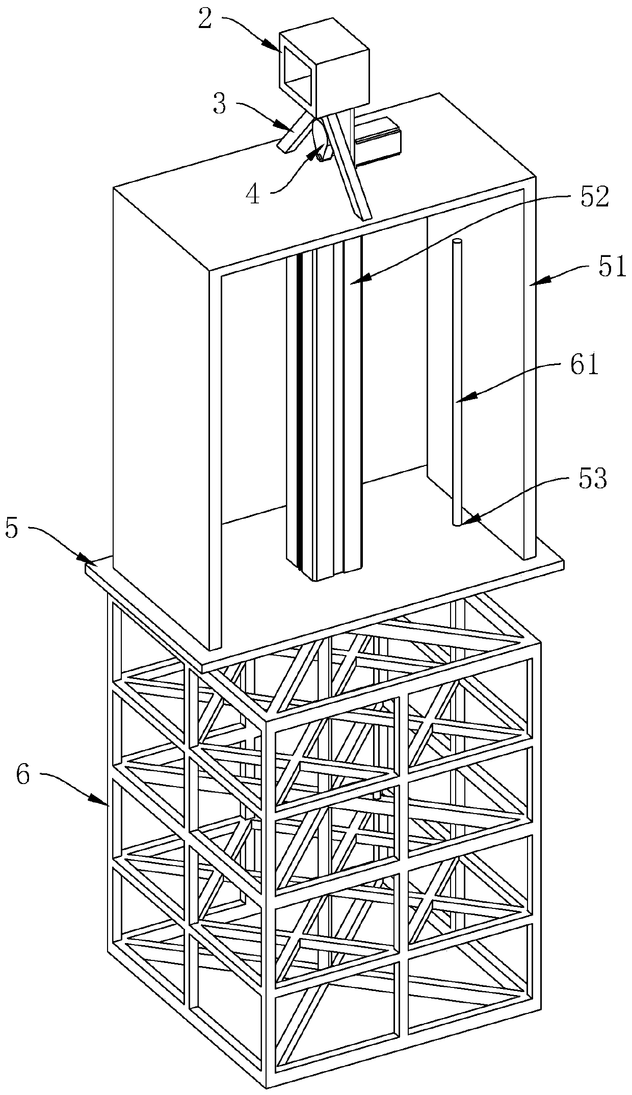
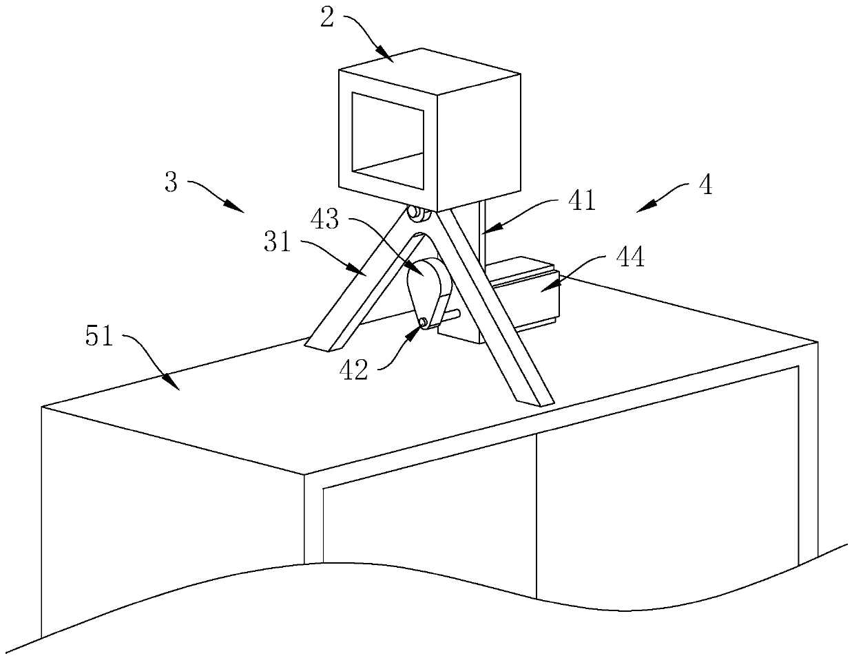
[0071] Such as figure 1 , figure 2 As shown, a sliding seat 2 is horizontally slidably connected to the beam 11, and the lower end surface of the sliding seat 2 is hingedly provided with a supporting seat 3, and the lower end surface of the sliding seat 2 is provided with a driving mechanism 4 for driving the supporting seat 3 to reciprocate and swing.

[0072] Such as figure 1 , figure 2 As shown, a mounting base 5 is provided below the support base 3 , and a gantry frame 51 is provided on the upper end surface of the mounting base 5 , and the upper end of the g...


PUM


Abstract

The invention discloses a production process for an oil tank and relates to the field of oil tank machining. The production process comprises the following steps of S1, plate shearing; S2, stamping; S3, edge shearing; S4, punching; S5, welding; S6, airtightness detection; S7, cleaning; and S8, plastic spraying. The production process for the oil tank has the following advantages and effects that the oil tank is subjected to acid pickling, neutralizing, phosphating and water washing in sequence to form a layer of phosphating film on the surface of the oil tank, the later adhesive force of a paint film and the corrosion resistant capability of the surface of the oil tank are improved, and therefore, the product quality of the produced oil tank is improved.

Description

technical field [0001] The invention relates to the field of fuel tank processing, in particular to a production process for fuel tanks. Background technique [0002] A generator is a mechanical device that converts other forms of energy into electrical energy, and the fuel tank is a container for fuel on the generator. [0003] Chinese patent CN108555546A discloses an improved automobile fuel tank processing technology, including S1, uncoiling and blanking; S2, stamping and spot welding of the fuel tank; S3, bending and straight edge welding of the fuel tank; S4, flange and welding of the tank body; S5, fuel tank End cover molding; S6, fuel tank molding and testing. [0004] After the above-mentioned fuel tank is processed and shaped, it is usually necessary to clean and paint the fuel tank. However, when cleaning, usually only the impurities on the surface of the fuel tank are initially cleaned. The product quality after the production of the fuel tank has been reduced a...

Claims


Application Information

Patent Timeline
Patent Type & Authority Applications(China)
IPC IPC(8): B23P15/00C23G3/00C23C22/73B01D29/03B01D29/64
CPCB01D29/03B01D29/64B23P15/00C23C22/73C23G3/00
Inventor 施丹阳王付周华章强
Owner 杭州樱多电器有限公司
Why Eureka
Try Eureka