
Belt guide machine for textile processing

A belt guide and machine body technology, which is applied in the field of belt guide machines for textile processing, can solve the problems of affecting the overall rotation speed of the conveying roller, the inability to automatically tension the guide belt, and poor conveying stability, so that it is not easy to wear and fluff, and avoids falling down. thorn, reduce the effect of error

Active Publication Date: 2020-03-27
扬州森杰机械制造有限公司
View PDF8 Cites 0 Cited by
  • Summary
  • Abstract
  • Description
  • Claims
  • Application Information

AI Technical Summary

Problems solved by technology

[0002] In the process of textile processing, the belt guide machine is an indispensable device, which can realize the transmission of the textile belt and improve the processing efficiency. The belt guide machines currently used are simple in structure and poor in adaptability. When the conveying roller is worn out, the conveying stability is poor. It cannot be automatically tensioned to adapt to the guide belt. In addition, some guide belts will have burrs due to long-term use. The burrs will be stuck in the roller body and the conveyor roller will continue to move. The torn fiber is involved by the conveying roller, which affects the overall rotation speed of the conveying roller, resulting in speed deviation, and inconsistent tightness after weaving finished products

Method used


Image

  • Belt guide machine for textile processing
  • Belt guide machine for textile processing
  • Belt guide machine for textile processing

Examples


Embodiment

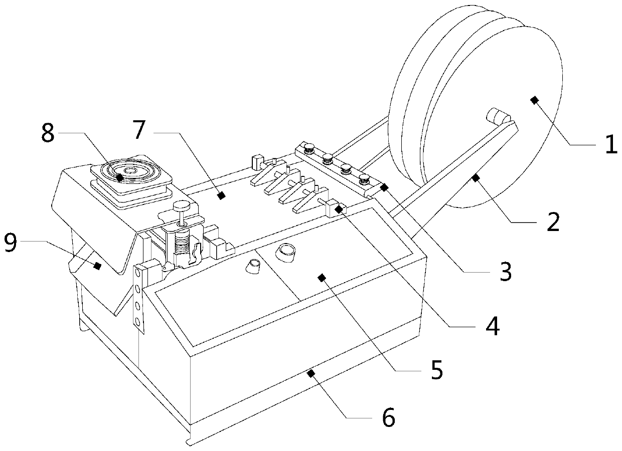
[0027] see Figure 1-Figure 5 , the present invention provides a belt guide machine for textile processing, the structure of which includes a discrete disc 1, a bracket 2, an elastic adjustment mechanism 3, a wire disc 4, a control panel 5, a body 6, a platform 7, a cutting knife 8, and an outlet 9, The top of the body 6 is a platform 7, the two ends of the platform 7 are respectively provided with a wire reel 4 and a cutting knife 8, an outlet 9 is provided directly below the cutting knife 8, and one side of the platform 7 of the body 6 is provided with a Control panel 5, the outer side of the wire reel 4 away from the cutting knife 8 is equipped with a tightness adjustment mechanism 3, and the other side of the tightness adjustment mechanism 3 is equipped with a bracket 2, and the bracket 2 is equipped with more than two discrete disks 1, used to separate the conduction band.

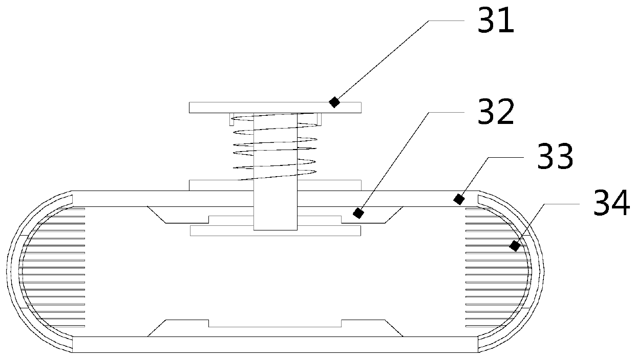
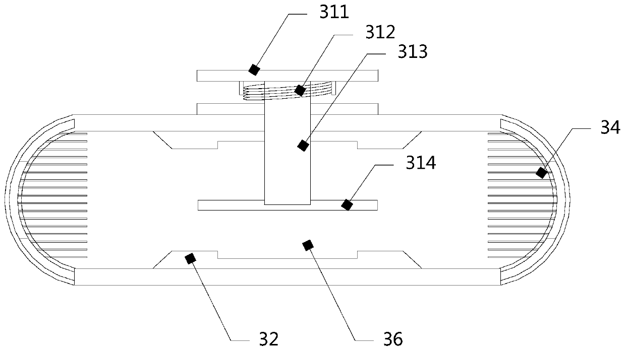
[0028] The tension adjusting mechanism 3 is provided with an elastic device 31 and a casing 33, a...


PUM


Abstract

The invention discloses a belt guide machine for textile processing. The belt guide machine comprises vertical dividing discs, a support, a tightness adjusting mechanism, a guide disc, a control panel, a machine body, a platform, a cutter and an outlet. The platform is arranged at the top end of the machine body. The two ends of the platform are provided with the guide disc and the cutter respectively. The outlet is formed right below the cutter. The control panel is arranged on one side of the platform of the machine body. The outer side, away from the cutter, of the guide disc is provided with the tightness adjusting mechanism. The support is installed on the other side of the tightness adjusting mechanism. Two or more vertical dividing discs are installed on the support and used for separating a guide belt. Springs and a pressing plate of the tightness adjusting mechanism cooperate with each other, tightness adjustment of the guide belt is achieved in the vertical direction, symmetrical elastic strips are arranged on the inner wall of a shell to adjust the guide belt, rigid collision caused by contact of the guide belt is reduced, abrasion of the guide belt is relieved, barbs are avoided, the surfaces of the elastic strips are smooth, the friction coefficient of the guide belt and the elastic strips is low, and the guide belt is not prone to abrasion or fluffing.

Description

technical field [0001] The invention relates to the field of textile equipment, in particular to a belt guide machine for textile processing. Background technique [0002] In the textile processing process, the belt guide machine is an indispensable device, which can realize the transmission of the textile belt and improve the processing efficiency. The belt guide machines currently used are simple in structure and poor in adaptability. When the conveying roller is worn, the conveying stability is poor. It cannot be automatically tensioned to adapt to the guide belt. In addition, some guide belts will have burrs due to long-term use. The burrs will be stuck in the roller body and the conveyor roller will continue to move. The torn fiber is involved by the conveying roller, which affects the overall rotation speed of the conveying roller, resulting in speed deviation, and inconsistent tightness after weaving the finished product. Contents of the invention [0003] Aiming a...

Claims


Application Information

Patent Timeline
IPC IPC(8): B65D25/10B65D85/68C25D13/22
CPCB65H23/26
Inventor 谢雄星邱惠峰
Owner 扬州森杰机械制造有限公司
Learn More