A gap photolithography mechanism and photolithography method thereof

A gap and lithography technology, applied in the field of lithography, can solve the problems of shortening the service life of the mask, contamination of the mask, and low qualification rate, and achieves the improvement of appearance quality defects, obvious appearance defects, and improved appearance defects. Effect

Active Publication Date: 2022-04-08
ZHONGHANG ELECTRONICS MEASURING INSTR
View PDF9 Cites 0 Cited by
  • Summary
  • Abstract
  • Description
  • Claims
  • Application Information

AI Technical Summary

Problems solved by technology

Therefore, the level of photolithography technology and the quality will directly affect the line quality of the resistance strain gauge pattern after etching, and ultimately affect the appearance qualification rate and product performance of the resistance strain gauge product.
[0003] As we all know, the conventional photolithography process of the resistance strain gauge pattern, whether it is the lithography process of the film flex plate or the chrome plate lithography process, adopts the traditional contact lithography process technology, that is, the pre-fabricated film flex plate or chrome plate mask The plate is directly contacted with the photoresist layer of the resistance strain gauge flexible foil plate that has been coated with photoresist through vacuum adsorption. Extrusion can easily cause damage to the surface of the photoresist and the surface of the mask. At the same time, the mask is also easy to stick to the photoresist, causing mask pollution, which not only shortens the service life of the mask, but also continuously Repeated use will also seriously affect the photolithographic quality of the resistance strain gauge foil, resulting in defects in the appearance of strain gauge lines such as bridges, gaps, broken grids, and redundant objects, making the pass rate of the product in this process low.

Method used


Image

  • A gap photolithography mechanism and photolithography method thereof
  • A gap photolithography mechanism and photolithography method thereof

Examples


Embodiment Construction

[0029] In order to make the purpose, technical solutions and advantages of the embodiments of the present invention clearer, the technical solutions of the present invention will be clearly and completely described below in conjunction with the accompanying drawings. Obviously, the described embodiments are part of the embodiments of the present invention, not all of them. the embodiment. Based on the embodiments of the present invention, all other embodiments obtained by persons of ordinary skill in the art without making creative efforts belong to the protection scope of the present invention.

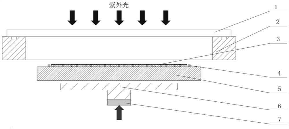
[0030] In order to solve the problems of the traditional contact photolithography process in the production process of resistance strain gauges, such as mask damage, many appearance defects of product lines, and low process pass rate, the present invention provides a gap photolithography mechanism and its photolithography method, Such as figure 1 As shown, as a specific embodiment o...


PUM

PropertyMeasurementUnit
surface smoothnessaaaaaaaaaa

Abstract

The invention discloses a gap photolithography mechanism and a photolithography method thereof, comprising a mask holder, the mask holder is a hollow structure with two ends open, the upper end surface of the mask holder is used to place a mask plate, the mask holder A film holder is provided below the mask frame, the upper end surface of the film holder is used to place the flexible foil board, and a number of limit posts are arranged around the area for placing the flexible foil board, and the upper end surface of the stop post is Higher than the photoresist surface of the flexible foil plate, the film carrier can enter the mask frame; when the film carrier enters the mask frame, and the upper end surface of the limit post is aligned When the film surface of the mask is in contact, there is a gap between the film surface of the mask plate and the photoresist surface of the flexible foil board. The present invention can form a fixed gap between the drug film surface of the mask plate and the photoresist surface of the flexible foil plate during photolithography, avoiding the contact between the two, thereby improving the utilization rate of the mask plate and greatly improving the quality of the product. Appearance quality defects improve the pass rate of products.

Description

technical field [0001] The invention belongs to the technical field of lithography, and in particular relates to a gap lithography mechanism and a lithography method thereof. Background technique [0002] Photolithography is a key step in the manufacturing process of resistance strain gauges. Before the resistance strain gauge pattern is etched, it is necessary to form a specific strain gauge photoresist pattern through a photolithography process. Therefore, the level of photolithography process and the quality will directly affect the line quality of the resistance strain gauge pattern after etching, and ultimately affect the appearance qualification rate and product performance of the resistance strain gauge product. [0003] As we all know, the conventional photolithography process of the resistance strain gauge pattern, whether it is the lithography process of the film flex plate or the chrome plate lithography process, adopts the traditional contact lithography process...

Claims


Application Information

Patent Timeline
Patent Type & Authority Patents(China)
IPC IPC(8): G03F7/20
CPCG03F7/20G03F7/70733
Inventor 晏志鹏张勋赵凯锋赵家辉刘旭赵恒花肖航高艳霞
Owner ZHONGHANG ELECTRONICS MEASURING INSTR
Why Eureka
Try Eureka