Continuous casting crack risk prediction method and application thereof

A technology of risk prediction and continuous casting slabs, applied in geometric CAD, design optimization/simulation, etc., can solve problems that cannot be raised, achieve convenient guidance, intuitive results, and improve porosity

Active Publication Date: 2020-03-27
NORTHEASTERN UNIV
View PDF13 Cites 2 Cited by
  • Summary
  • Abstract
  • Description
  • Claims
  • Application Information

AI Technical Summary

Problems solved by technology

[0008] The above continuous casting crack control method is to reduce the risk of crack initiation in the process and to explain the principle of crack initiation in theory, but fails to propose a method for predicting crack initiation and assessing the crack risk on site

Method used


Image

  • Continuous casting crack risk prediction method and application thereof
  • Continuous casting crack risk prediction method and application thereof
  • Continuous casting crack risk prediction method and application thereof

Examples


Embodiment 1

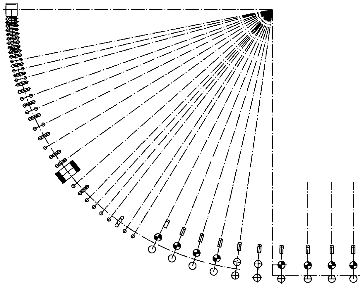
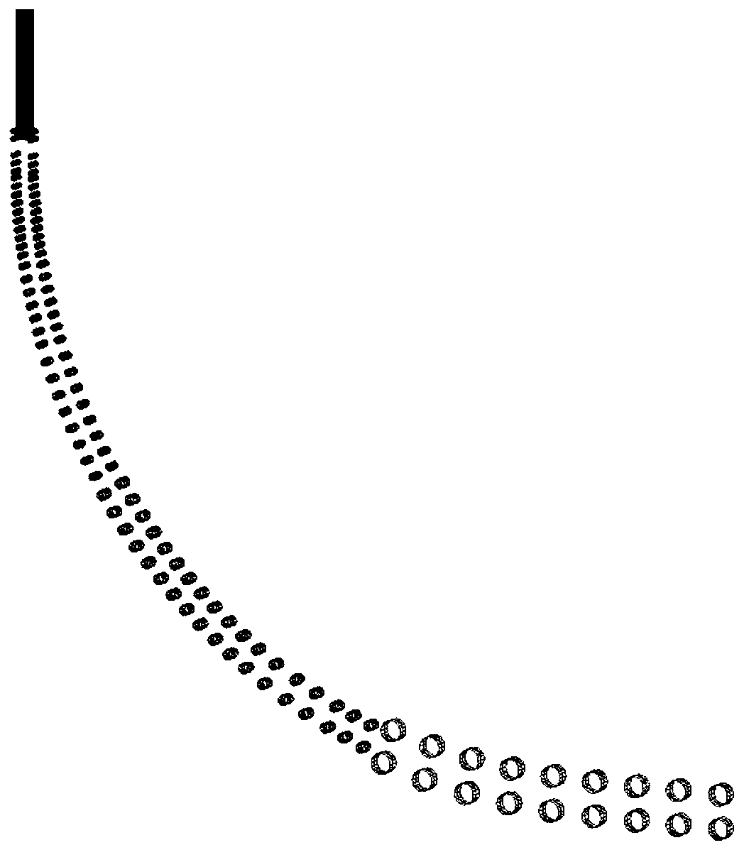
[0038] In this embodiment, the continuous casting production of GCr15 bearing steel with a cross-sectional size of 410mm×530mm is taken as an example. It adopts the solid-liquid two-phase region at the end of the solidification of the continuous casting slab, and implements the continuous casting light reduction technology. The casting speed of the casting machine is 0.58m / min, and keep the casting speed stable, select the nodes on the middle surface of the billet casting direction as the object, and study the variation of the tensile strain at each position on the middle surface with the position of the strand. The monitoring surface is shown in Figure 4 , When the reduction of 1~9# tension leveling machine is 0 / 1 / 1 / 1 / 2 / 3 / 4 / 4 / 2mm respectively, the schematic diagram of each position on the middle surface and the change of tensile strain with time, and analyze the crack Risk cloud map.

[0039] A method for predicting the risk of continuous casting slab cracks in this embodime...

Embodiment 2

[0046] In this embodiment, the continuous casting production cross-sectional size is 300mm * 2200mm Q345E microalloy steel wide and thick slab, the caster casting speed is 0.80m / min, and the casting speed is kept stable;

[0047] A method for predicting the risk of continuous casting slab cracks in this embodiment comprises the following steps:

[0048] Step 1: Select the critical strain for initiation of intermediate cracks in Q345E steel as the criterion for crack initiation. Specifically, the critical strain for initiation of intermediate cracks in Q345E steel in this embodiment is 0.04.

[0049] Step 2: According to the continuous casting process parameters for microalloy wide and thick slabs, import the geometric dimensions of each equipment in the continuous casting process into MSC.Marc finite element software, and establish in the finite element software from the mold meniscus to air cooling The thermal / mechanical coupling model of the whole process of continuous casti...

Embodiment 3

[0052] In this example, TiMo microalloy steel with a cross-sectional size of 200mm×1200mm is produced by continuous casting, the casting speed of the casting machine is 1.1m / min, and the casting speed is kept stable, and the occurrence rate of cracks at the corners of the surface of the wide and thick slab is relatively high , has a greater impact on the production of slabs, and the addition of microalloying elements also increases crack sensitivity. A TiMo microalloyed steel with high microalloy content was selected as the research object, and the critical criterion for crack propagation at the corner of the TiMo microalloyed steel wide and thick slab, the simulation results of temperature and deformation, and the crack risk prediction model were used to determine the risk of crack growth at the corner. for analysis.

[0053] Its continuous casting slab crack risk prediction method includes the following steps:

[0054] Step 1: Select the critical strain for crack propagatio...


PUM


Abstract

The invention discloses a continuous casting crack risk prediction method and an application thereof, and belongs to the technical field of continuous casting. According to the continuous casting crack risk prediction method, as intermediate cracks are generated in the continuous casting process and surface crack propagation is mainly caused by tensile strain or tensile stress, the tensile strainis taken as a basis for judging middle crack initiation and surface crack propagation, and a crack risk prediction model is established on the basis of a critical crack criterion of high-temperature tensile measurement and a full-flow heat / force coupling model of continuous casting from the meniscus of a crystallizer to the end of an air cooling area. A crack risk prediction model is adopted to analyze the crack risk of the casting blank in the whole continuous casting process and draw a crack risk cloud chart, so that a process strategy is provided for field production to control crack defects, and the quality of the casting blank is improved.

Description

technical field [0001] The invention relates to the technical field of continuous casting, in particular to a method for predicting crack risks of continuous casting slabs and its application. Background technique [0002] Cracks are one of the main quality problems of continuous casting slabs, and cracks account for about 50% of all kinds of defects. The root causes of crack formation are the phase transformation of the slab during continuous casting, the precipitation behavior of carbonitrides at the grain boundaries, and the performance differences between different microstructures. There is a zero plasticity temperature (ZDT) in the high temperature zone, and the material near the ZDT temperature is between the solid phase and the liquid phase, with poor fluidity and low plasticity, and cracks are easily generated in this temperature range; in the low temperature zone of the austenite phase, due to Dynamic recovery and dynamic recrystallization are difficult to occur, a...

Claims


Application Information

Patent Timeline
Patent Type & Authority Applications(China)
IPC IPC(8): G06F30/17G06F30/23B22D11/00
CPCB22D11/00
Inventor 祭程张晋源李国梁朱苗勇
Owner NORTHEASTERN UNIV
Why Eureka
Try Eureka