Round hole center positioning device, device for drawing line between centers of round holes and device for measuring distance between centers of round holes
A center positioning and positioning disc technology, which is applied in the direction of measuring/indicating equipment, metal processing machinery parts, metal processing equipment, etc., can solve the problems of low efficiency and high positioning cost, and achieve convenient manufacturing, high versatility, and simple structure Effect
- Summary
- Abstract
- Description
- Claims
- Application Information
AI Technical Summary
Problems solved by technology
Method used
Image

Examples
Embodiment 1
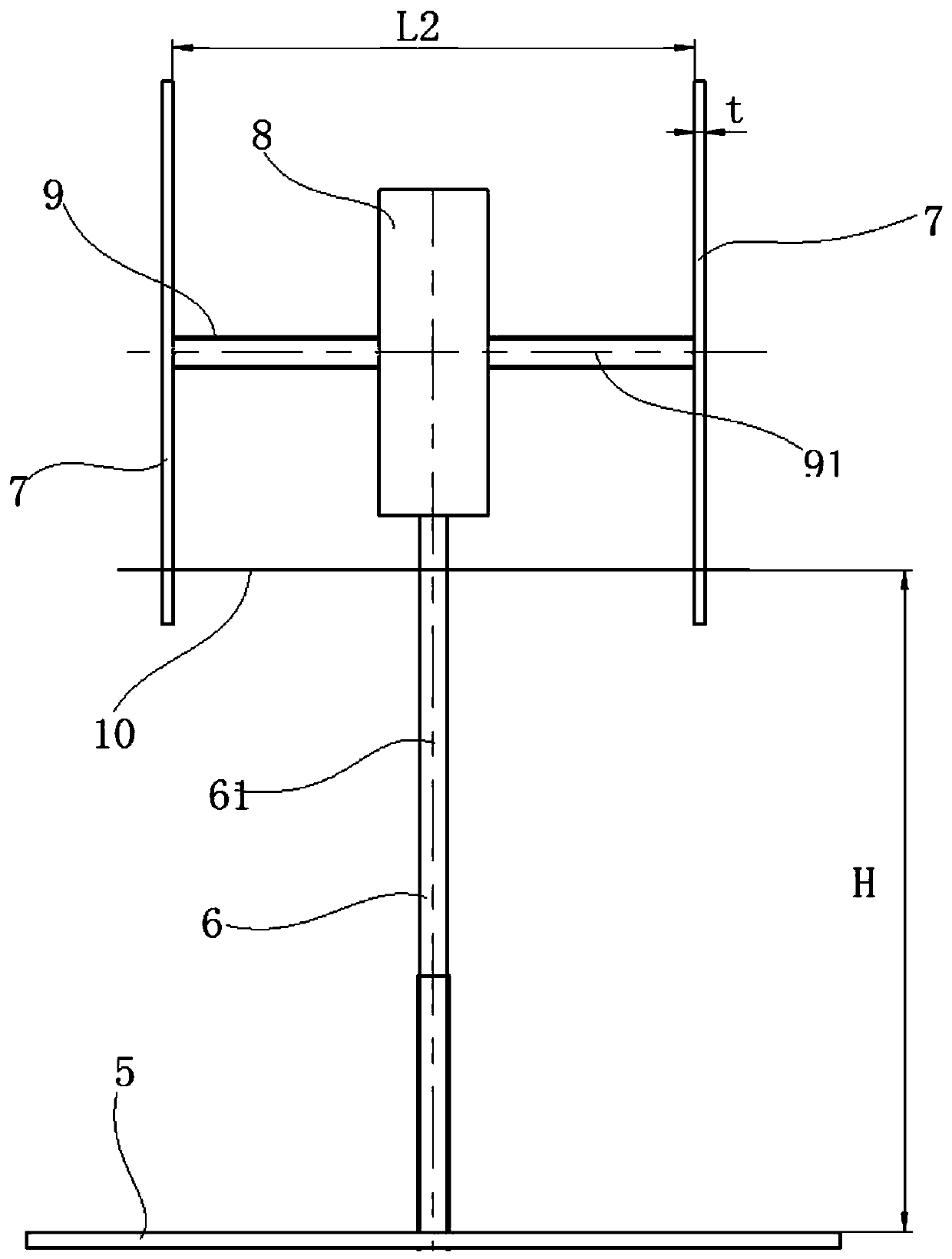
[0031] Such as Figure 1 to Figure 4 As shown, the center positioning device of the circular hole in this embodiment is used to determine the center (center) of a circular hole whose two ends are flat. On the workpiece, the circular hole 10 is a through hole, and the circular hole 10 The planes on which the end faces at both ends are located are parallel to each other.
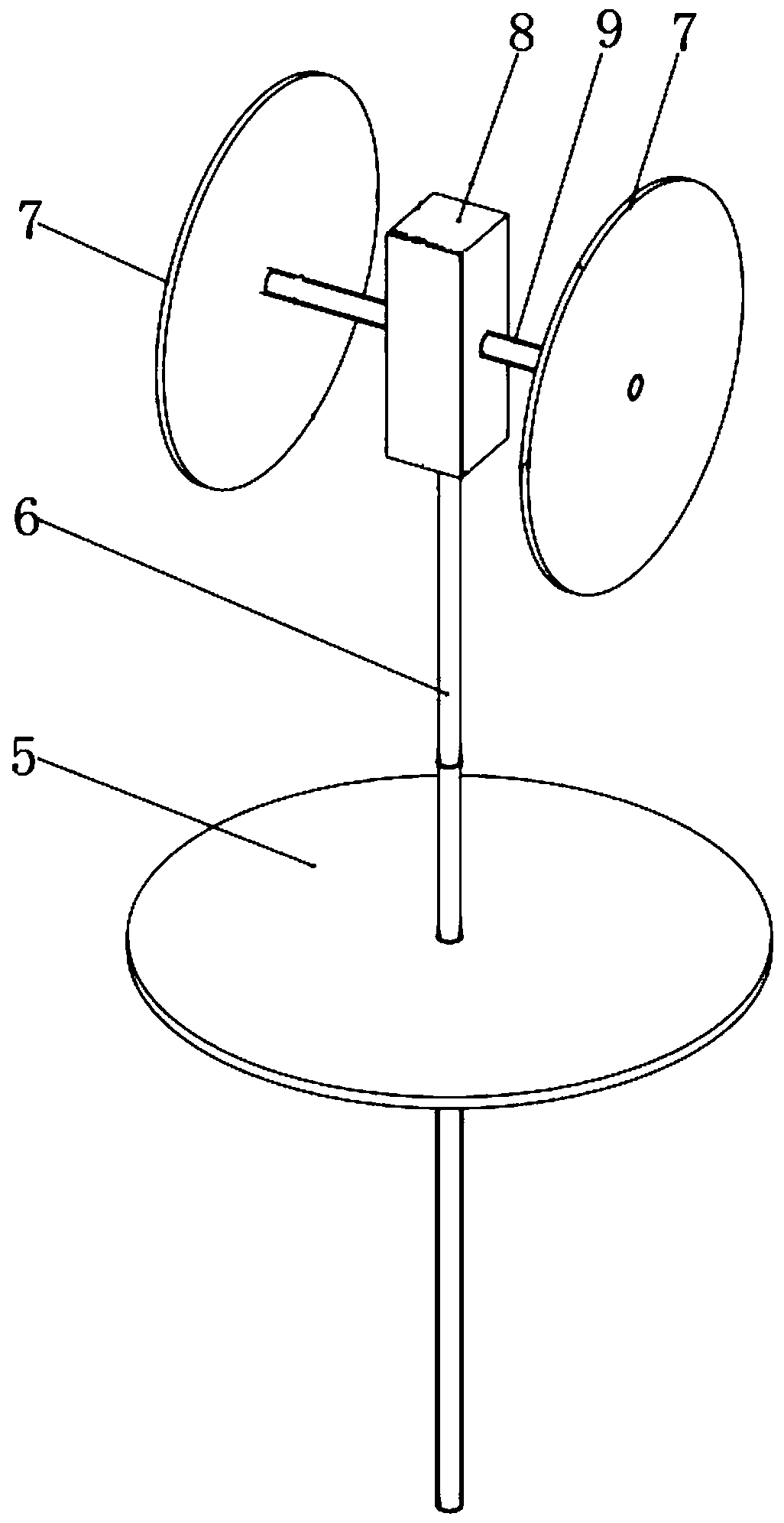
[0032] Such as figure 1 As shown, the center positioning device for the circular hole includes two positioning discs 7 of equal diameter, a vertical threaded connecting rod 6, a positioning plate 5, and a connecting part. The connecting part is used to install the positioning disc 7 and the vertical threaded connecting rod 6, which includes a connecting block 8 and a transverse connecting rod 9 fixed laterally on the connecting block. The two positioning discs 7 are arranged coaxially and fixed or fixed respectively. The upper end of the vertical threaded connecting rod 6 is connected with the connecting block 8,...
Embodiment 2
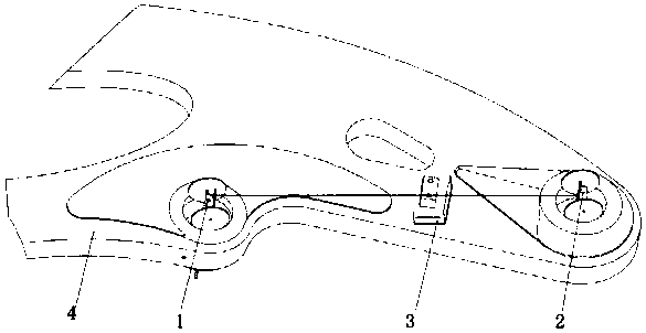
[0040] Figure 5 to Figure 9 The drawing device between the centers of the circular holes in this embodiment is shown. The line drawing device between the center of the circular hole includes two circular hole center positioning devices and the line drawing bending plate 3 in embodiment 1. The circular hole center positioning devices are the first circular hole center positioning device 1 and the second circular hole center respectively Positioning device 2.
[0041] Such as Figure 5 Image 6 As shown, in the first circular hole center positioning device 1, the connecting block 8 is provided with a vertical sliding groove 81, and a slider 82 is provided in the sliding groove 81. The sliding direction of the slider 82 is the same as the vertical threaded connecting rod 6 The axis 61 is parallel. The slider 82 is provided with a screw 84 and a beam emitting device 83. When the slider 82 is slid to a proper position, the slider 82 can be locked with the connecting block 8 by the s...
Embodiment 3
[0046] Such as Picture 10 As shown, this embodiment shows a device for measuring the distance between the centers of circular holes. In this device, its structure is basically the same as the first circular hole center positioning device 1 and the second circular hole center positioning device 2 in the second embodiment. The difference is that there is no need to draw a line bending plate 3 in the distance measuring device between the centers of the circular holes, and the beam emitting device 83 can not only emit a light beam, but also has a distance measurement function. When measuring the distance between the centers of two circular holes, the first circular hole center positioning device 1 and the second circular hole center positioning device 2 are respectively placed on the two circular holes of the structure under test, first visually perform rough aiming, and adjust the beam emitting device 83 And the direction of the light receiving plane, so that the light beam emitte...
PUM
 Abstract
Description
Claims
Application Information
 - R&D
- Intellectual Property
- Life Sciences
- Materials
- Tech Scout
- Unparalleled Data Quality
- Higher Quality Content
- 60% Fewer Hallucinations
Browse by: Latest US Patents, China's latest patents, Technical Efficacy Thesaurus, Application Domain, Technology Topic, Popular Technical Reports.
© 2025 PatSnap. All rights reserved.Legal|Privacy policy|Modern Slavery Act Transparency Statement|Sitemap|About US| Contact US: help@patsnap.com