

Rare earth halide scintillating material
A technology of scintillation materials and halides, which is applied in the direction of scintillation components, luminescent materials, chemical instruments and methods, etc., can solve problems such as crystal growth defects, affecting the uniformity of crystal performance, inconsistent doping concentration, etc., and achieve the effect of improving the yield
- Summary
- Abstract
- Description
- Claims
- Application Information
AI Technical Summary
Problems solved by technology
Method used
Image

Examples
Embodiment 1
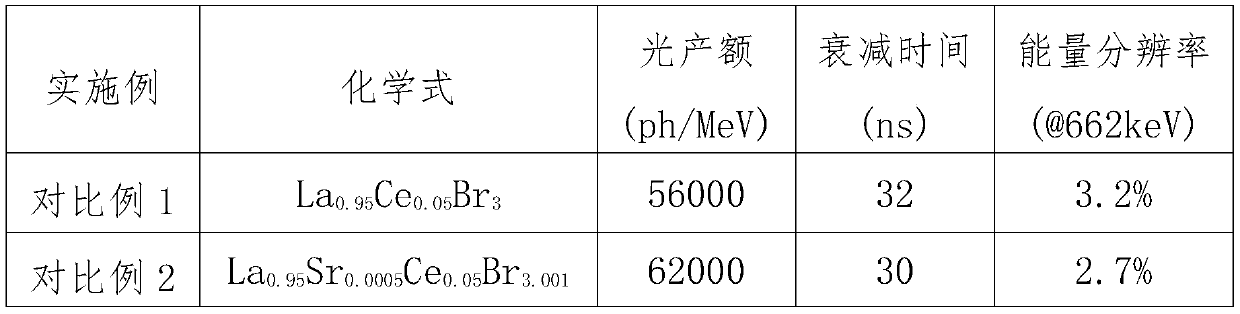
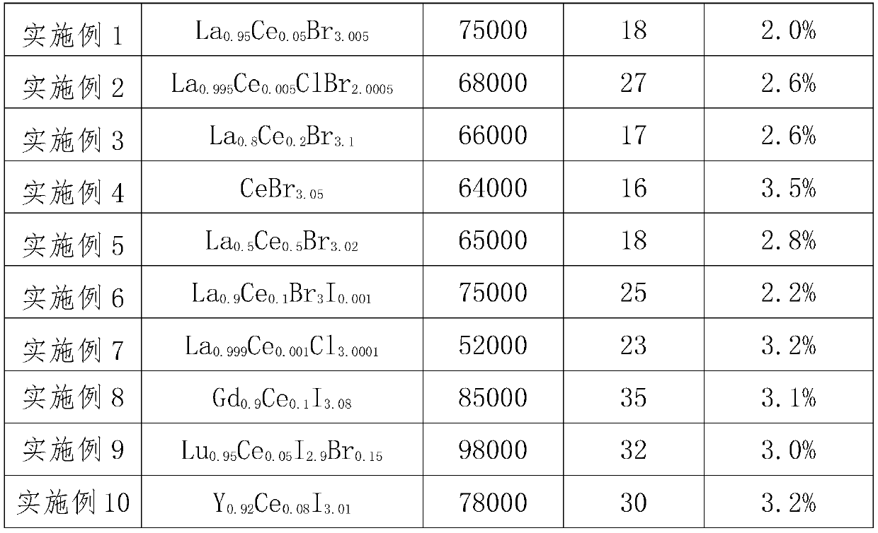
[0044] Embodiment 1: Accurately weigh 119.89g anhydrous LaBr in the Ar glove box 3 (99.99%) and 6.46g anhydrous CeBr 3.1 (99.99%), after mixing evenly, pack into a quartz crucible with a diameter of 25mm. All the other operations are the same as in Comparative Example 1.
[0045] Embodiment 2-10 is all the same as embodiment 1 except that the ratio of raw materials is different.
[0046] The detailed comparative situation of all embodiments is shown in Table 1.
[0047] Table 1
[0048]
[0049]
[0050] In summary, the present invention provides a kind of rare earth halide scintillation material, the chemical general formula of this rare earth halide scintillation material is RE 1-m Ce m x 3+n , wherein RE is one of rare earth elements La, Gd, Lu, Y, X is one or two of Cl, Br, I, 0.001≤m≤1, 0.0001≤n≤0.1. The rare earth halide scintillation material obtained in the present invention has excellent scintillation performance, and its overall performance is obviously ...
PUM
 Abstract
Description
Claims
Application Information