Novel wood structure column base joint reinforcement structure and construction method thereof

A technology of column base joints and reinforced structures, applied in the direction of columns, pier columns, pillars, etc., can solve the problems of structural damage of round wooden columns, failure to consume internal force of round wooden columns, damage of round wooden columns, etc., to reduce internal force and avoid tilting or serious collapse and damage, and the effect of improving safety

Pending Publication Date: 2020-03-31
SOUTH CHINA UNIV OF TECH
View PDF8 Cites 7 Cited by
  • Summary
  • Abstract
  • Description
  • Claims
  • Application Information

AI Technical Summary

Problems solved by technology

[0003] The utility model patent with the notification number CN207597720U discloses an anti-seismic node structure of a wooden column foot, by pre-embedding the ring-shaped flange steel plate and the vertical arc-shaped steel sheet in the foundation of the wooden column foot, the steel sheet and the round wooden column Fixing with bolts controls the displacement of the column foot. This method completely limits the slippage of the column foot, but it cannot consume the internal force of the round wooden column, and it will still cause damage to the round wooden column, and the steel sheet and the round wooden column pass through. The bolts are fixed, and the bolts pass through the round wooden pillars, and the round wooden pillars must be drilled to artificially damage the structure of the round wooden pillars

Method used


Image

  • Novel wood structure column base joint reinforcement structure and construction method thereof
  • Novel wood structure column base joint reinforcement structure and construction method thereof
  • Novel wood structure column base joint reinforcement structure and construction method thereof

Examples


Embodiment

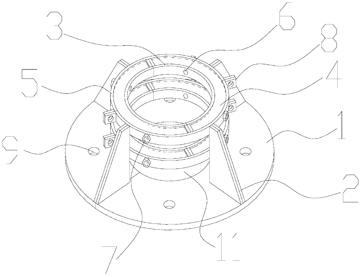
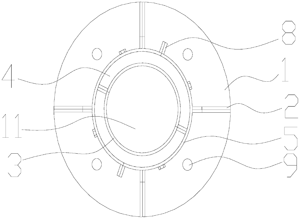
[0031] Such as figure 1 with figure 2 As shown, this embodiment is a new type of wood structure column foot node reinforcement structure, including a steel base plate 1, a plurality of reinforcements 2 and two hoop assemblies.

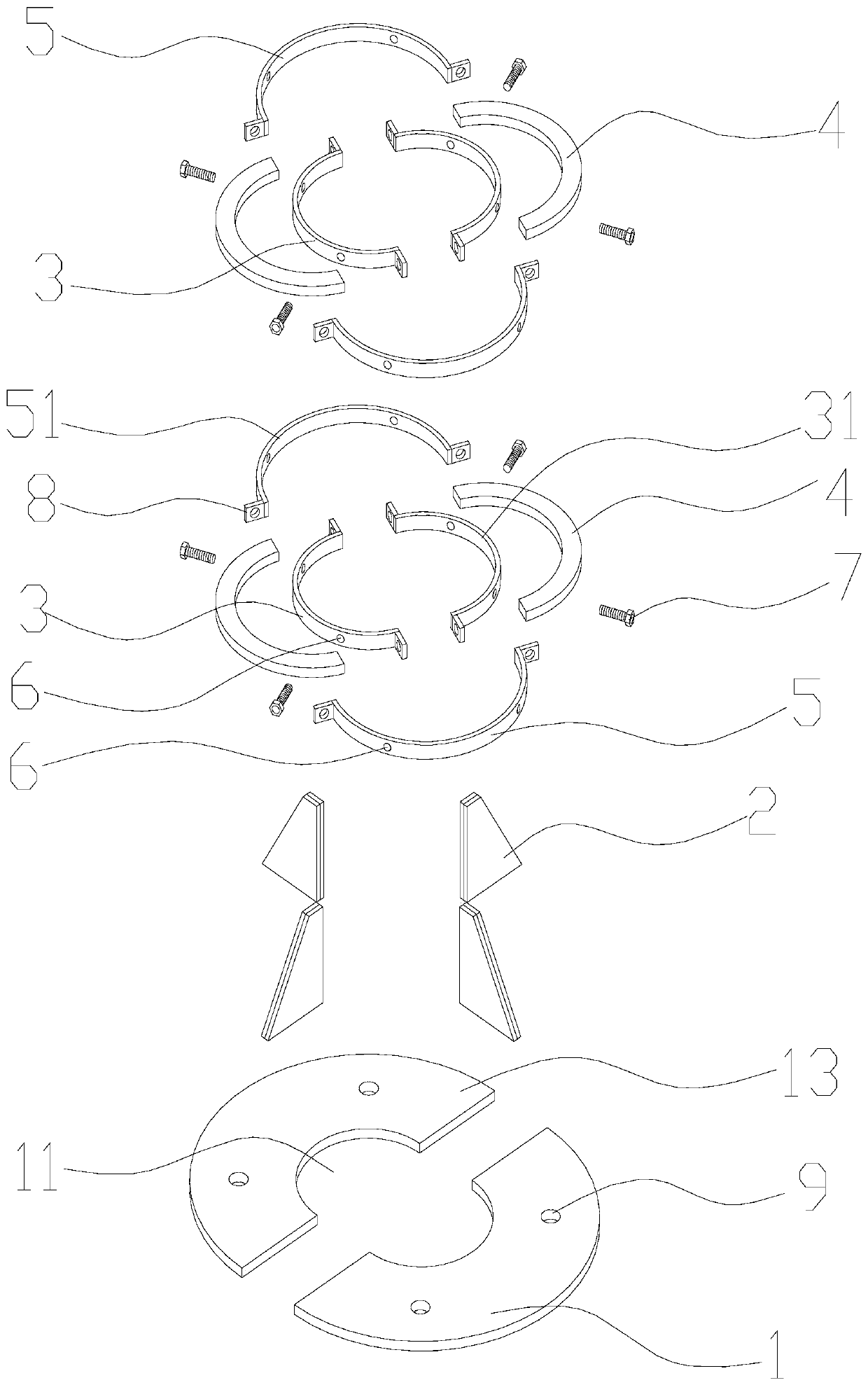
[0032] Such as figure 1 with image 3 As shown, the two hoop assemblies are respectively arranged at different levels of the column foot. The hoop assembly includes an inner hoop 3, an elastic member 4 and an outer hoop 5. The inner hoop is set outside the column foot 20, and the inner hoop The inner diameter of the hoop matches the cross-sectional diameter of the column foot, the outer hoop is set outside the inner hoop, the elastic part is clamped between the outer hoop and the inner hoop, the elastic part is a rubber ring, the inner hoop, the outer hoop and the A plurality of positioning holes 6 are correspondingly provided on the rubber ring, and the bolts 7 pass through the positioning holes on the inner hoop, the outer hoop and the rubber rin...


PUM


Abstract

The invention discloses a novel wood structure column base joint reinforcement structure and a construction method thereof. The reinforcement structure comprises a steel bottom plate, multiple reinforcement pieces and at least one hoop assembly. Each hoop assembly comprises an inner hoop, an elastic piece and an outer hoop. The inner hoops are arranged outside a column base in a sleeving manner. The inner diameter of the inner hoops is matched with the section diameter of the column base. The outer hoops are arranged outside the inner hoops. The elastic pieces are clamped between the outer hoops and the inner hoops. A column base hole is formed in the steel bottom plate. The steel bottom plate is fixed to foundation stone where the column base is placed. The column base is located in the column base hole. The diameter of the column base hole is larger than the diameter of the column base. The reinforcement pieces are fixed to the steel bottom plate and are connected with the outer sidewalls of the outer hoops. According to the novel wood structure column base joint reinforcement structure, by arranging the elastic pieces between the inner hoops and the outer hoops, when the columnbase slides, the inner hoops and the column base slide together in a limited manner; and shock absorption energy consumption is achieved through elastic deformation of the elastic pieces, and the improvement of the overall safety of wood structures is facilitated.

Description

technical field [0001] The invention relates to the technical field of wood structure engineering, in particular to a novel wood structure column base node reinforcement structure and a construction method thereof. Background technique [0002] my country's traditional wooden structure buildings have a major structural feature, that is, the wooden column feet are placed directly on the foundation stone at the bottom. In recent decades, scholars at home and abroad have carried out a lot of research on this structural feature, and have greatly appreciated it as a modern sliding vibration isolation bearing. It is true that when an earthquake occurs, a certain lateral movement of the column foot can slow down the large internal force of the frame, but many people have found that the displacement of the column foot is also a form of failure, and some suggestions for strengthening the column foot joints have also been proposed. The innovative design idea and applied for a patent,...

Claims


Application Information

Patent Timeline
Patent Type & Authority Applications(China)
IPC IPC(8): E04C3/36E04G23/02E04B1/98E04H9/02E04G21/00
CPCE04C3/36E04G23/0218E04B1/98E04H9/02E04G21/00
Inventor 蔡健陈俊霖巫博璘陈庆军左志亮杨春姜正荣
Owner SOUTH CHINA UNIV OF TECH
Why Eureka
Try Eureka