Ejector, chilled beam tail end and chilled beam system

A technology of ejector and chilled beam, applied in chilled beam system, ejector, chilled beam end field, can solve the problems of high control technology and detection feedback technology, high application cost and unnecessary

Pending Publication Date: 2020-03-31
GREE ELECTRIC APPLIANCES INC
View PDF0 Cites 0 Cited by
  • Summary
  • Abstract
  • Description
  • Claims
  • Application Information

AI Technical Summary

Problems solved by technology

[0004] The existing methods of driving the thimble (shaft needle) of the injector mainly include the electromagnetic drive type, which is similar to the driving principle of the electronic expansion valve. The corresponding technology of this method is the most mature and the most reliable design, which is suitable for very high precision requirements. conditions of use, but the requirements for its control technology and detection feedback technology are also high, and for general applications, its application cost is high and it is not necessary. Design a high reliability, simple structure, easy maintenance with adjustable The chilled beam end of the injector in the throat area is extremely necessary

Method used


Image

  • Ejector, chilled beam tail end and chilled beam system
  • Ejector, chilled beam tail end and chilled beam system
  • Ejector, chilled beam tail end and chilled beam system

Examples


Embodiment Construction

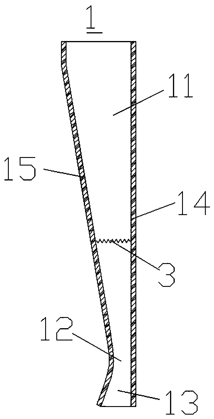
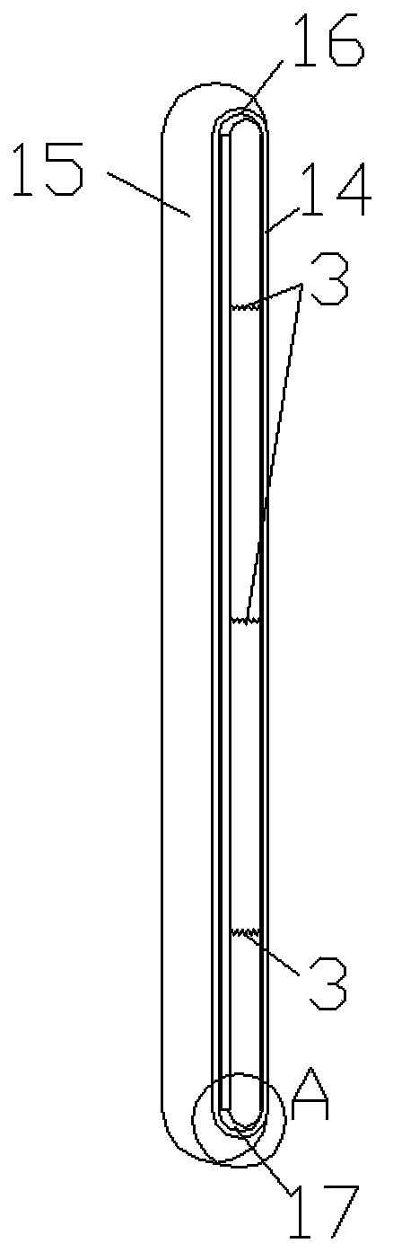
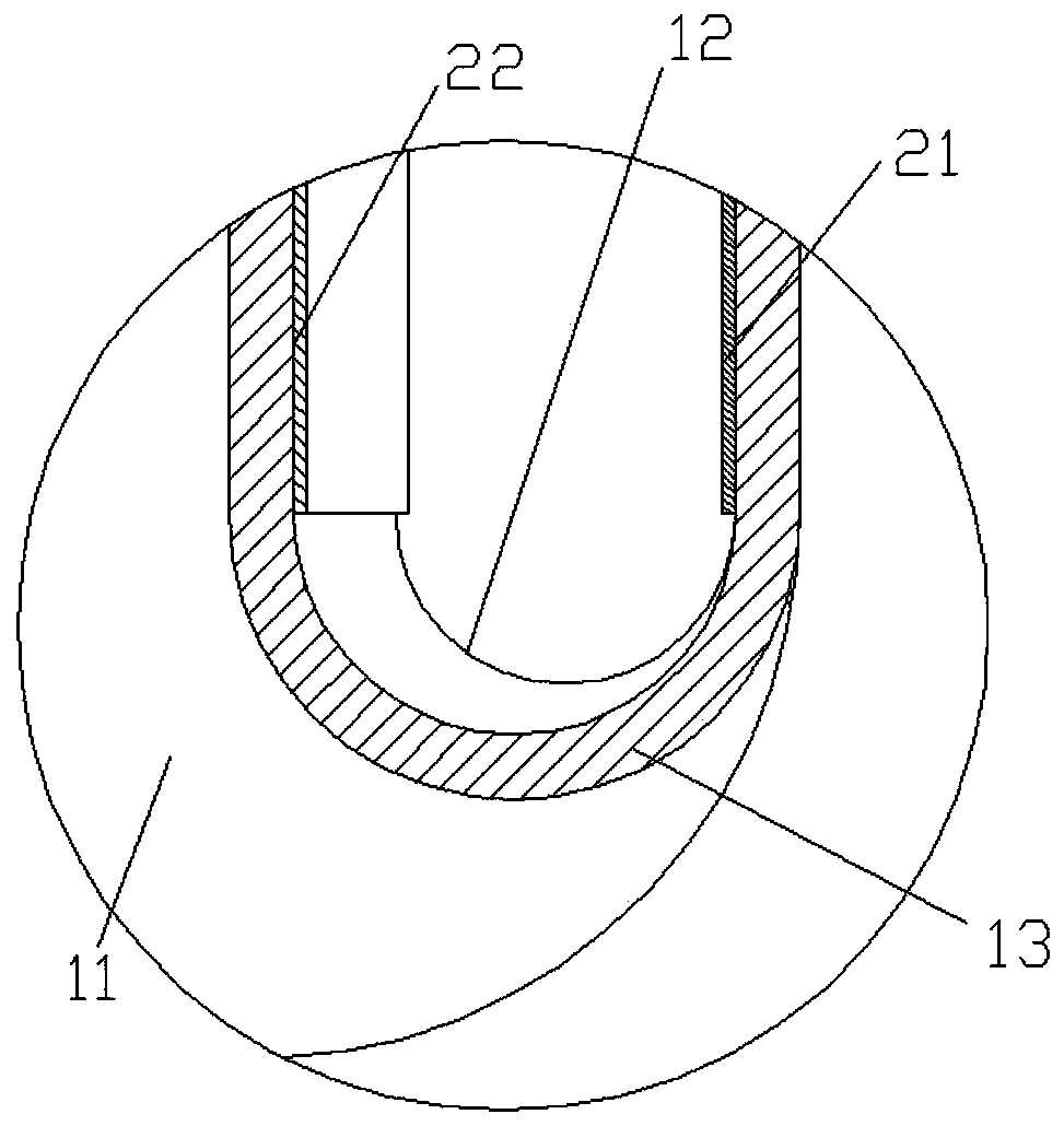
[0023] see in conjunction Figure 1 to Figure 4 As shown, according to an embodiment of the present invention, an injector is provided for use in the end of a chilled beam, comprising a nozzle housing 1, the nozzle housing 1 includes an airflow introduction section 11 for introducing primary air, for The nozzle throat 12 for throttling and accelerating the introduced primary air, and the airflow output section 13 for ejecting the throttled and accelerated primary air, the nozzle throat 12 is located between the airflow introduction section 11 and the airflow output section Between 13, when the wind pressure of the primary wind changes, the nozzle housing 1 can be elastically deformed to change the flow area of ​​the nozzle throat 12 . In this technical solution, since the nozzle housing 1 can be elastically deformed, when the primary wind pressure therein changes, the nozzle housing 1 will undergo elastic deformation under the action of the primary wind pressure, thereby The ...


PUM


Abstract

The invention provides an ejector, a chilled beam tail end and a chilled beam system. The ejector comprise a nozzle shell, the nozzle shell comprises an airflow leading-in section used for leading inprimary air, a nozzle throat part used for conducting throttling acceleration on the led-in primary air, and an airflow output section used for spraying out the throttled and accelerated primary air;the nozzle throat part is located between the airflow leading-in section and the airflow output section; and when the air pressure of the primary air changes, the nozzle shell can elastically deform so as to change the through-flow area of the nozzle throat part. According to the ejector, the chilled beam tail end and the chilled beam system, the nozzle shell can make elastic deformation when theprimary air pressure changes, then the through-flow area of the throat of the nozzle is changed, the structure is simple, the reliability is high, maintenance is convenient, and the cost is low.

Description

technical field [0001] The invention belongs to the technical field of air conditioning, and in particular relates to an injector, a chilled beam end, and a chilled beam system. Background technique [0002] The existing active chilled beams use nozzles to make the primary air spray at a high speed to induce the secondary return air in the room, and the primary air and the secondary air are mixed and sent into the room. Under the same cooling capacity conditions, the greater the induction ratio (secondary air volume: primary air volume, generally about 3:1, that is, the injection coefficient), the smaller the primary air volume, but the greater the pressure loss and noise value of the primary air. [0003] In the variable air volume system, the injection coefficient of the injector at the end of the chilled beam varies greatly, and often deviates from the design value, resulting in performance degradation or even failure. Therefore, quality adjustment or volume adjustment is...

Claims


Application Information

Patent Timeline
IPC IPC(8): F24F13/26F24F1/0007
CPCF24F1/0007F24F13/26
Inventor 黄玉优王子平谢文利李超
Owner GREE ELECTRIC APPLIANCES INC
Why Eureka
Try Eureka