Rolling forced vibration dynamic derivative test device for high-speed flying wing model under large attack angle

A test device and dynamic derivative technology, applied in aerodynamic tests, measuring devices, aircraft component testing, etc., can solve dynamic stability and control constraints The wide application of flying wing layout aircraft, lack of control efficiency, uncontrollable instability, etc. problems, to achieve the effect of improving stability and smoothness, improving stiffness and improving measurement accuracy

Active Publication Date: 2020-03-31
CHINA ACAD OF AEROSPACE AERODYNAMICS
View PDF8 Cites 10 Cited by
  • Summary
  • Abstract
  • Description
  • Claims
  • Application Information

AI Technical Summary

Problems solved by technology

However, there are obvious shortcomings in the dynamic stability and control of flying-wing layout aircraft. Flying in the edge area of ​​​​the stable boundary will cause uncontrolla

Method used


Image

  • Rolling forced vibration dynamic derivative test device for high-speed flying wing model under large attack angle
  • Rolling forced vibration dynamic derivative test device for high-speed flying wing model under large attack angle
  • Rolling forced vibration dynamic derivative test device for high-speed flying wing model under large attack angle

Examples


Embodiment

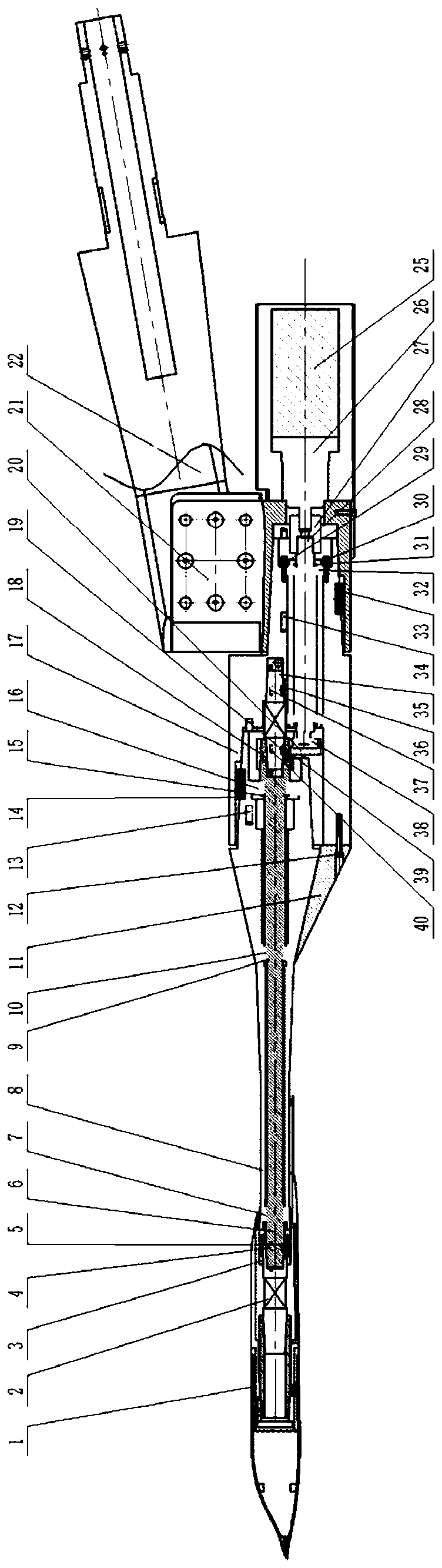
[0065] When using the roll forced vibration dynamic derivative test device of the present invention under the large angle of attack of the high-speed flying wing model to carry out the test, the 10 ° turning head of the device is installed on the scimitar of the wind tunnel, and the front end of the signal measuring device and the flying wing model Connected together, the theoretical center of mass of the test model coincides with the rotation line of the signal measuring device, the motor drive device is controlled to rotate at a specified frequency through the motor control system, and the amplitude is adjusted through the eccentric shaft 28, so that the model can perform a simple harmonic of the specified frequency and amplitude sports. During the test, the force, torque signal and angular displacement signal of the signal measuring device are measured synchronously, and the corresponding dynamic stability derivative can be obtained by corresponding processing of the two sig...


PUM

PropertyMeasurementUnit
Lengthaaaaaaaaaa
Angle daaaaaaaaaa
Lengthaaaaaaaaaa

Abstract

The invention discloses a rolling forced vibration dynamic derivative test device for a high-speed flying wing model under a large attack angle. The rolling forced vibration dynamic derivative test device comprises a rigid support device, a motor driving device, a motion conversion device, a simple harmonic motion angle measurement device, a simple harmonic motion transmission device, a five-component dynamic load measurement device and a dynamic derivative test model; and the rigid supporting device supports the whole test mechanism, and the tail end is directly installed on a wind tunnel bent blade arm. The motor driving device is a power source, provides continuous rotary motion output for the whole set of test mechanism and is mounted at the tail part of the rigid supporting device; the motion conversion device converts the continuous rotating motion into required simple harmonic motion, and the angle time history of the simple harmonic motion is measured through the simple harmonic motion angle measuring device; the simple harmonic motion transmission device transmits motion to the five-component dynamic load measuring device, the dynamic derivative test model is installed onthe five-component dynamic load measuring device, and the dynamic derivative test model is subjected to dynamic load in the simple harmonic motion process of the five-component dynamic load measuringdevice; and signal processing is performed on the measured dynamic load time history and the simple harmonic motion angle time history so as to obtain a required dynamic derivative value.

Description

technical field [0001] The invention relates to a wind tunnel test device for measuring the dynamic derivative in the rolling direction of a high-speed flying wing model under a large attack angle by means of a small-amplitude forced vibration method. Background technique [0002] The aerodynamic design and control system design of the aircraft require the dynamic stability derivative data of the aircraft under its flight conditions. When the aircraft changes its attitude or is disturbed by the air flow, it will produce pitch, yaw or roll vibrations that deviate from the equilibrium attitude. The purpose of dynamic stability research is to predict the attenuation trend and law of these vibrations. For aircraft with passive damping control, the dynamic flight quality and reliability requirements of the aircraft put forward extremely high requirements for the prediction of the dynamic stability of the aircraft. Too low dynamic stability will easily lead to the divergence of ...

Claims


Application Information

Patent Timeline
IPC IPC(8): G01M9/00G01M9/04G01M9/06B64F5/60
CPCB64F5/60G01M9/00G01M9/04G01M9/06
Inventor 刘金宋玉辉胡静陈兰秦汉王方剑
Owner CHINA ACAD OF AEROSPACE AERODYNAMICS
Why Eureka
Try Eureka