
Optical observation window capable of being used in high-temperature and high-pressure environment

A high temperature and high pressure, observation window technology, applied in the direction of applying stable tension/pressure to test the strength of materials, measuring devices, scientific instruments, etc. Achieving the effect of wide application, reducing safety hazards, and simple cleaning and maintenance

Active Publication Date: 2020-03-31
AECC SICHUAN GAS TURBINE RES INST
View PDF6 Cites 1 Cited by
  • Summary
  • Abstract
  • Description
  • Claims
  • Application Information

AI Technical Summary

Problems solved by technology

Although the flange structure can meet the requirements of high-temperature and high-pressure gas sealing, the light-transmitting material of the observation window is often weaker than the material of the flange in terms of hardness and toughness. Material damage or even chipping
In addition, the manual installation of multiple bolts has problems such as poor control of the bolt tightening torque, and inconsistent tightening torque of each bolt, which leads to stress in the light-transmitting material, which makes this type of observation window have hidden dangers such as gas leakage and cracking of the light-transmitting material during application. When there is high-speed airflow, rotating equipment, etc. inside the test piece, such hidden dangers will be magnified many times due to the existence of vibration
On the other hand, light-transmitting materials often need to be wiped and cleaned after each test, and they need to be reinstalled after maintenance. Repeated installation and disassembly are not only time-consuming and laborious, but also further reduce the assembly quality of the window

Method used


Image

  • Optical observation window capable of being used in high-temperature and high-pressure environment

Examples


Embodiment Construction

[0021] The present invention will be further explained below in conjunction with accompanying drawing

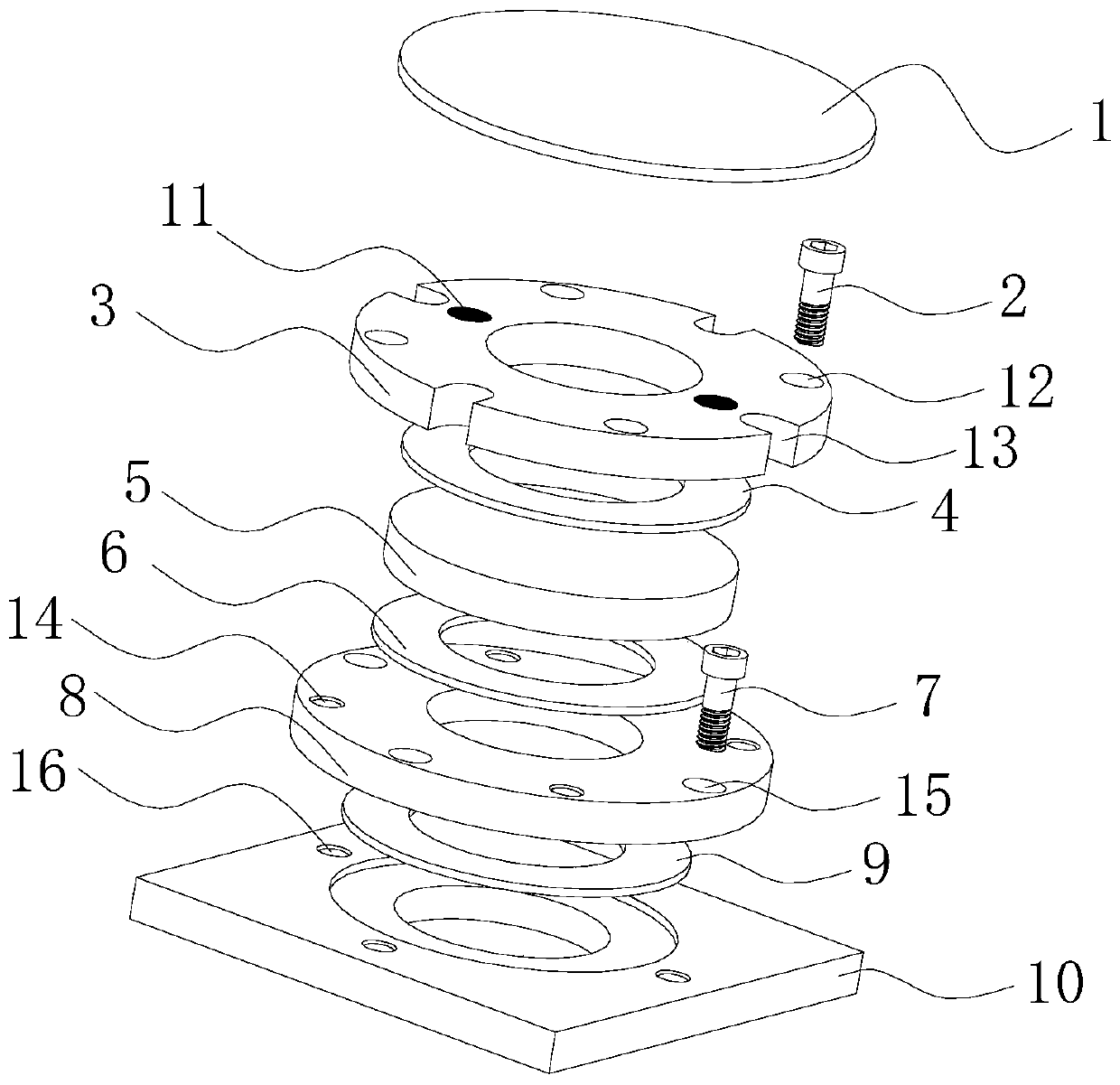
[0022] Such as figure 1 As shown, it is an optical observation window that can be used in high temperature and high pressure environment provided by the present invention. The optical observation window includes a protective cover plate 1, an upper flange plate 3, an upper sealing gasket 4, a light-transmitting material 5, a lower sealing gasket 6, a lower flange plate 8 and a sealing gasket for installing the observation window arranged in sequence 9;

[0023] The observation window also includes an observation window assembly bolt 2 and a bolt 7 for installing the observation window;

[0024] The observation window assembly bolt 2 is used to assemble the observation window assembly;

[0025] The bolts 7 for installing the observation window are used to install the observation window on the observation object.

[0026] A magnet 11 is buried on the upper flange, and the ...


PUM


Abstract

The invention provides an optical observation window capable of being used in a high-temperature and high-pressure environment. The observation window comprises a protective cover plate (1), an upperflange plate (3), an upper sealing gasket (4), a light-transmitting material (5), a lower sealing gasket (6), a lower flange plate (8) and a sealing gasket (9) for installing the observation window, the observation window further comprises an observation window assembling bolt (2) and a bolt (7) for installing the observation window. The observation window assembly bolt (2) is used for assemblingan observation window assembly; and the observation window mounting bolt (7) is used for mounting the observation window on an observation object. The structure of the optical observation window capable of being used in the high-temperature and high-pressure environment avoids direct contact between a light-transmitting material and an observed piece, greatly reduces potential safety hazards whenthe observation window works, and has the advantages that mounting and dismounting are efficient, cleaning and maintaining are easy, the light-transmitting material is easy to replace, and a protective cover is convenient to use.

Description

technical field [0001] The invention belongs to the technical field of turbomachinery testing, and in particular relates to an optical observation window device that can be used in a high-temperature and high-pressure environment. Background technique [0002] In the tests of various types of machinery such as aero-engines, gas turbines, and internal-combustion engines, it is often necessary to perform optical observations on certain internal hot-end components. Since the internal hot-end specimens of this type of mechanical system are often in a closed environment of high-temperature (above 500°C) and high-pressure (above 1MPa) gas, it is only possible to set up an optical observation window at a specific position to meet requirements such as infrared temperature measurement. , spectrum shooting, visual measurement and other application requirements of various optical testing technologies. [0003] The existing observation window products in the domestic and foreign market...

Claims


Application Information

Patent Timeline
Patent Type & Authority Applications(China)
IPC IPC(8): G01N3/02G01N3/18
CPCG01N3/02G01N3/18Y02E30/30
Inventor 刘志刚杨明贺元赵旺东张帅
Owner AECC SICHUAN GAS TURBINE RES INST
Learn More