Temperature abnormal defect detecting and positioning method and system

A technology of abnormal defect and positioning method, applied in the field of abnormal temperature defect detection and positioning method and system, can solve the problems of high camera position requirements, difficult registration, insufficient judgment and positioning efficiency, etc., so as to improve registration efficiency and reduce computation. Quantity and temperature abnormality defect judgment and high positioning efficiency

Pending Publication Date: 2020-03-31
SHANTOU UNIV
View PDF5 Cites 12 Cited by
  • Summary
  • Abstract
  • Description
  • Claims
  • Application Information

AI Technical Summary

Problems solved by technology

[0008] The present invention provides a detection and positioning method for abnormal temperature defects in order to overcome the defects in the above-mentioned prior art that the registration of feature points for detection and

Method used


Image

  • Temperature abnormal defect detecting and positioning method and system
  • Temperature abnormal defect detecting and positioning method and system
  • Temperature abnormal defect detecting and positioning method and system

Examples


Embodiment 1

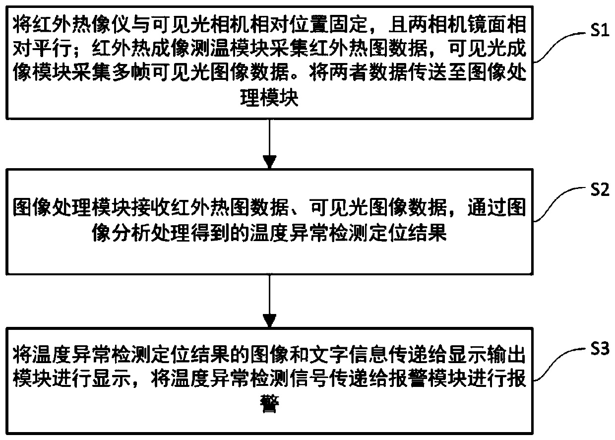
[0065] This embodiment provides a method for detecting and locating abnormal temperature defects, such as figure 1 As shown, the method includes the following steps:

[0066] S1: The relative positions of the infrared thermal imaging temperature measurement module and the visible light imaging module are fixed, and the mirror surfaces of the two are relatively parallel; the infrared thermal imaging temperature measurement module collects infrared heat map data, and the visible light imaging module collects visible light image data. Send the infrared heat map data and visible light image data to the image analysis and positioning module;

[0067] Wherein, in this embodiment, the infrared thermal imaging temperature measurement module is an infrared thermal imager, and the visible light imaging module is a visible light camera.

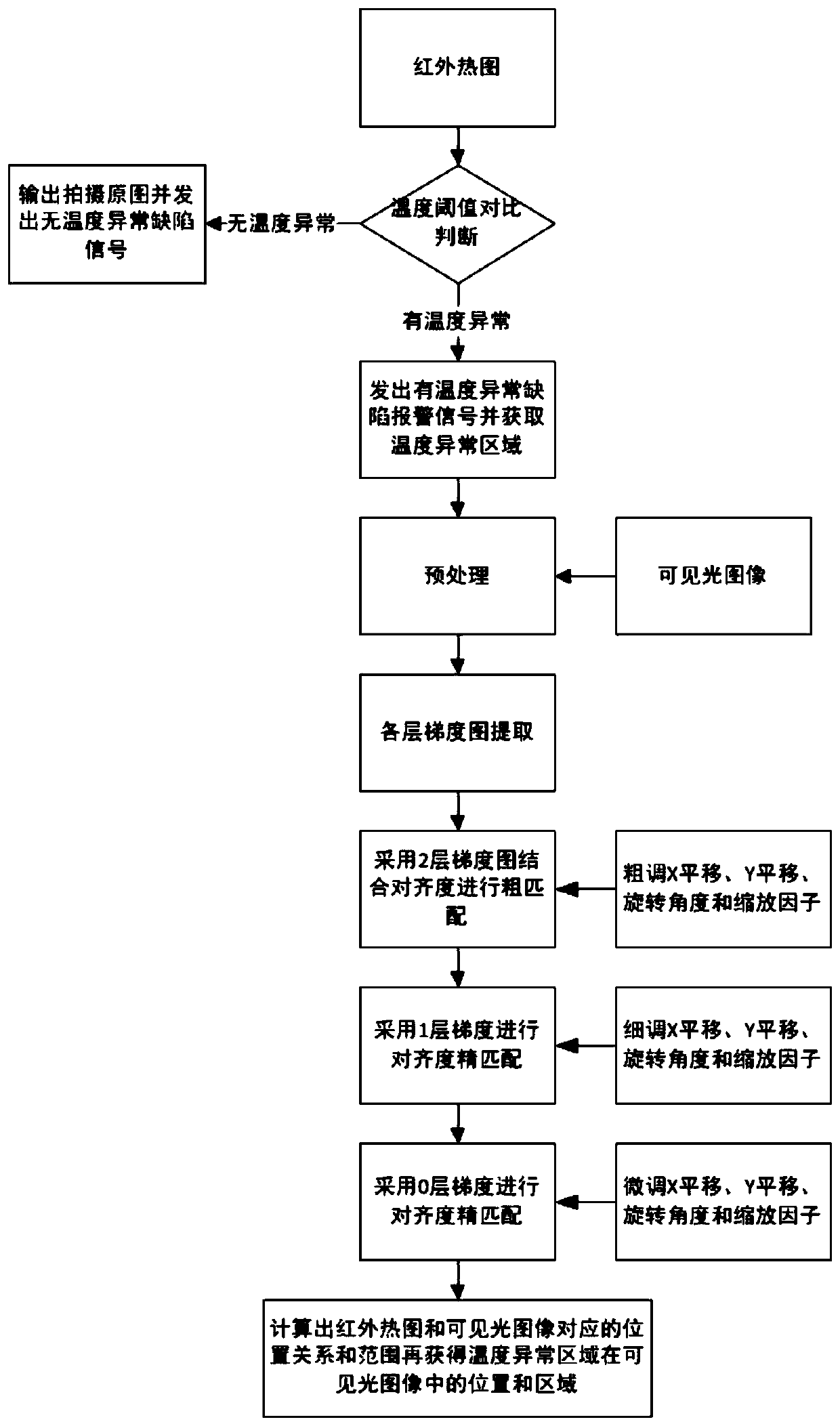
[0068] S2: The image analysis and positioning module receives infrared heat map data and visible light image data, and obtains temperature anomaly det...

Embodiment 2

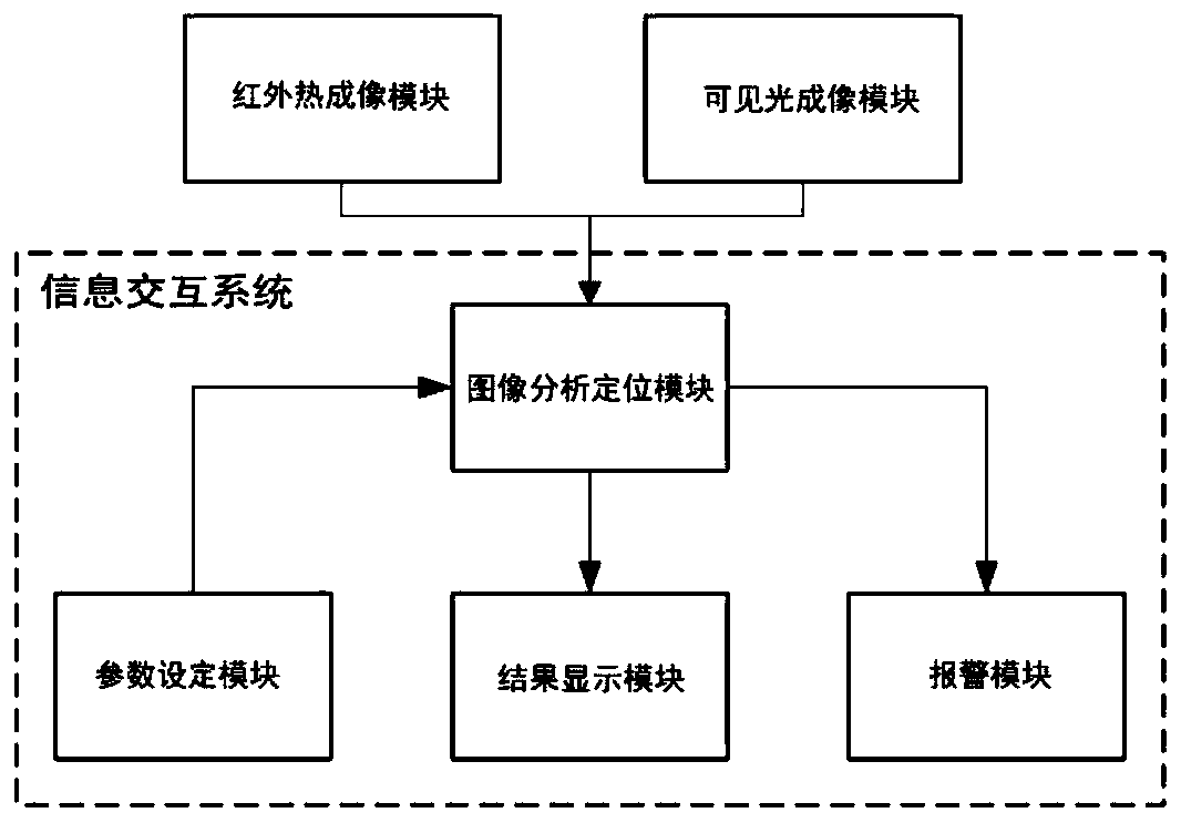
[0105] This embodiment provides a temperature anomaly defect detection and positioning system, such as image 3 As shown, the system includes: an infrared thermal imaging temperature measurement module, a visible light imaging module and an information interaction system, and the information interaction system includes a parameter setting module, a result display module, an alarm module, and an image analysis and positioning module; The imaging temperature measurement module collects the on-site infrared heat map, and transmits the infrared heat map data to the image analysis and positioning module; the visible light imaging module is used to collect the on-site visible light image, and transmits the visible light image data to the image analysis and positioning module; the parameters The setting module is used for the user to set the parameters of the infrared thermal imaging temperature measurement module, the parameter setting of the visible light imaging module, the result ...


PUM


Abstract

The invention relates to a temperature abnormal defect detection and positioning method and system. The system comprises an infrared thermal imaging temperature measurement module, a visible light imaging module, a parameter setting module, a result display module, an alarm module and an image analysis and positioning module. The method comprises the steps that S1, the relative positions of an infrared thermal imaging temperature measurement module and a visible light imaging module are fixed, and the mirror surfaces of the two modules are relatively parallel; the infrared thermal imaging temperature measurement module collects infrared thermal image data, and the visible light imaging module collects visible light image data; the data collected by the infrared thermal imaging temperaturemeasurement module and the visible light imaging module to an image analyzing and positioning module; s2, the image analyzing and positioning module receives the infrared thermogram data and the visible light image data, and obtains a temperature anomaly detection and positioning result through image analysis processing; and S3, the image and text information of the temperature anomaly detection positioning result are transmitted to a result display module for display, and a temperature anomaly detection signal is transmitted to an alarm module for alarming. According to the invention, the efficiency of temperature abnormal defect judgment and positioning can be improved.

Description

technical field [0001] The present invention relates to the field of detecting and locating abnormal temperature defects, and more specifically, to a method and system for detecting and locating abnormal temperature defects. Background technique [0002] For abnormal temperature defects, images are used for detection and positioning. Generally, infrared thermal imaging cameras are used to collect temperature data to obtain infrared temperature heat maps to locate abnormal temperature defects. However, the resolution of most thermal imaging cameras is low and much lower than that of ordinary visible light cameras, resulting in serious loss of details in infrared thermal images and blurred images. At present, the location of abnormal temperature defects is often determined based on the shooting position of the inspection robot or the shooting position of the technician. It requires staff familiar with the scene and infrared heat map to check remotely or enter the scene to dete...

Claims


Application Information

Patent Timeline
IPC IPC(8): G06T7/00G06T5/00G06T7/70G01J5/00
CPCG06T7/0002G06T5/002G06T7/70G01J5/00G06T2207/10048G06T2207/20032G06T2207/20036
Inventor 吴涛陈贤碧包能胜江惠宇李超平徐媛媛
Owner SHANTOU UNIV
Why Eureka
Try Eureka