
A kind of saturated steam treatment equipment for fiberboard raw material pulping

A technology for processing equipment and fiberboard, applied in transportation and packaging, chemical instruments and methods, chemical/physical processes, etc., can solve problems such as the inability to improve the utilization rate of saturated steam, reduce resource loss, ensure stable operation, and ensure efficiency Effect

Active Publication Date: 2022-06-24
山东欢哥装饰股份有限公司
View PDF7 Cites 0 Cited by
  • Summary
  • Abstract
  • Description
  • Claims
  • Application Information

AI Technical Summary

Problems solved by technology

[0005] In order to overcome the shortcomings that it is difficult to fully stir the fiberboard raw material and cannot improve the utilization rate of saturated steam, the technical problem is to provide a saturated steam treatment equipment for fiberboard raw material pulping that is convenient for fully stirring the fiberboard raw material and can improve the utilization rate of saturated steam

Method used


Image

  • A kind of saturated steam treatment equipment for fiberboard raw material pulping
  • A kind of saturated steam treatment equipment for fiberboard raw material pulping
  • A kind of saturated steam treatment equipment for fiberboard raw material pulping

Examples


Embodiment 1

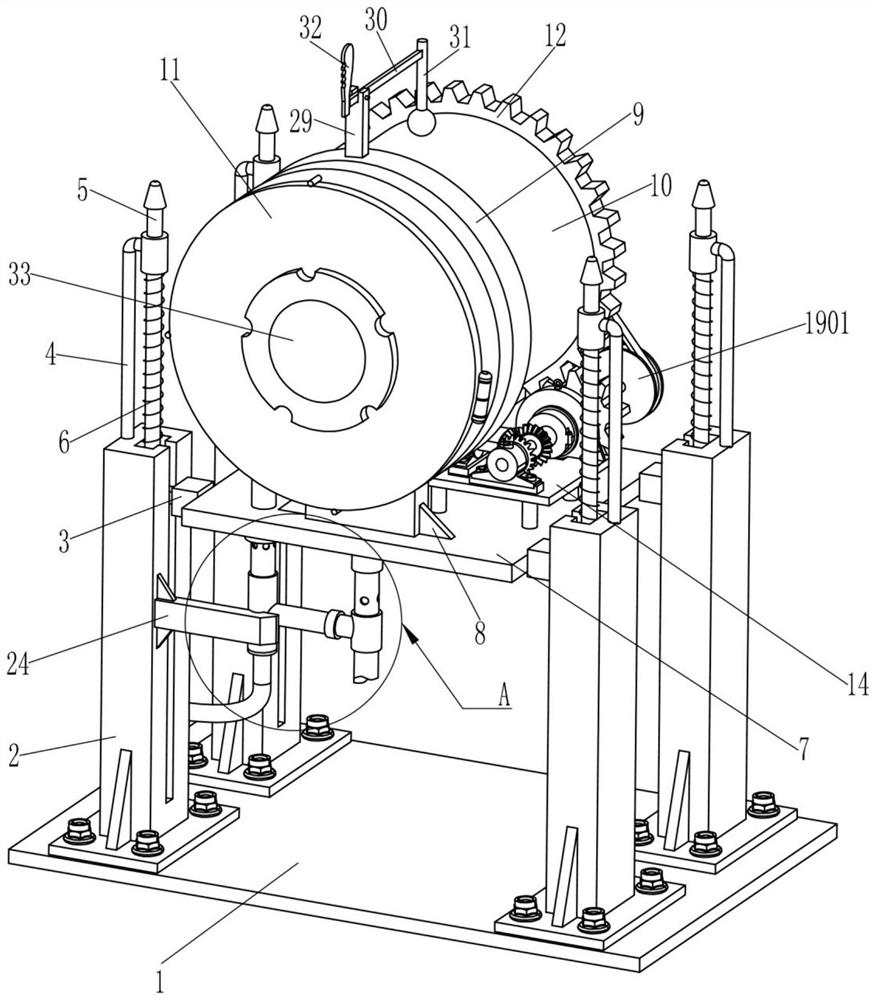
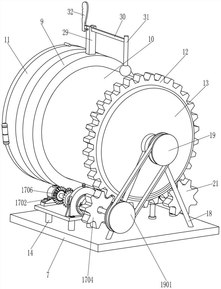
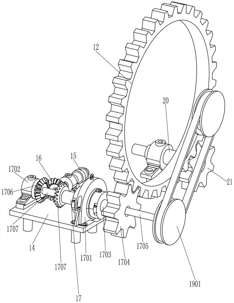
[0025] A saturated steam treatment equipment for fiberboard raw material pulping, such as Figure 1-6 As shown, it includes a bottom plate 1, a guide frame 2, a sliding plate 3, a guide frame 4, a guide rod 5, a first compression spring 6, a horizontal plate 7, a support seat 8, a slotted ring 9, a rotating opening cylinder 10, an opening and closing Assembly 11, gear ring 12, filter mesh cylinder 13, mounting plate 14, reduction motor 15, first bevel gear 16, reverse drive device 17, mounting seat 18, stirring device 19, base 20, second gear 21, air intake pipe 22 and the drain pipe 23, four guide frames 2 are arranged around the top of the bottom plate 1, the guide frame 2 is slidably connected with the sliding plate 3, the top of the guide frame 2 is provided with a guide frame 4, and the guide frame 4 is slidably connected with a guide frame. The rod 5, the first compression spring 6 is connected between the guide rod 5 and the guide frame 4, the inner side of the sliding ...

Embodiment 2

[0030] On the basis of Example 1, as Image 6 As shown, it also includes a mounting frame 24, a three-way pipe 25, a one-way valve 26, a guide sleeve 27 and an air intake hose 28. One side of the guide frame 2 is provided with a mounting frame 24, and the mounting frame 24 is provided with a three-way pipe. 25. The lower part of the intake pipe 22 is slidably located in the tee pipe 25, the tee pipe 25 is provided with a one-way valve 26, one end of the tee pipe 25 is provided with a guide sleeve 27, and the drain pipe 23 is slidably located in the guide sleeve 27, An air intake hose 28 is connected to the bottom end of the three-way pipe 25 .

[0031] When the horizontal plate 7 moves downward, the horizontal plate 7 drives the intake pipe 22 and the liquid discharge pipe 23 to move downward, and the liquid discharge pipe 23 and the intake pipe 22 are both provided with small holes. When the fiberboard material is used, the filter mesh cylinder 13 presses the horizontal plat...


PUM


Abstract

The invention relates to a saturated steam processing device, in particular to a saturated steam processing device for fiberboard raw material pulping. The technical problem of the present invention is how to provide a saturated steam treatment equipment for fiberboard raw material pulping that is convenient for fully agitating the fiberboard raw material and can improve the utilization rate of saturated steam. A saturated steam treatment device for fiberboard raw material pulping, including a bottom plate, a guide frame, a sliding plate, etc.; a plurality of guide frames are arranged around the top of the bottom plate, and a sliding plate is slidably connected to the inside of the guide frame. In the present invention, through the cooperation of the reverse drive device and the stirring device, the rotation speed of the rotating open cylinder is not consistent with the rotation speed of the stirring wheel, and the equipment can more fully stir the fiberboard raw material in the filter screen cylinder through the differential speed between the two. , ensuring the pulping efficiency of fiberboard raw materials.

Description

technical field [0001] The invention relates to a saturated steam treatment device, in particular to a saturated steam treatment device for fiberboard raw material pulping. Background technique [0002] Fiberboard, also known as density board, is a man-made board made of wood fiber or other plant fiber as raw material and applied with urea-formaldehyde resin or other suitable adhesives. Since fiberboard production raw materials need to be pulped, the fiberboard raw materials are separated into fibers. One process can be treated with saturated steam. In order to ensure that the saturated steam is in full contact with the fiberboard raw material, it is necessary to fully turn the fiberboard raw material during the heat treatment process. [0003] According to the existing invention, a straw fiberboard production system, the publication number of which is CN207846095U, is hereinafter collectively referred to as practical one, and practical one mainly describes the general produ...

Claims


Application Information

Patent Timeline
Patent Type & Authority Patents(China)
IPC IPC(8): B01F31/10B01F35/91B01F35/00
CPCB01F31/10B01F35/145B01F35/181B01F2035/99B01F35/91B01F2101/47
Inventor 黄春英
Owner 山东欢哥装饰股份有限公司
Learn More