
Gleeble thermal simulated test machine pipe extrusion mold and use method thereof

A technology of extrusion dies and testing machines, applied in the field of material processing, to achieve the effects of wide application, improved product quality, and simple structure

Pending Publication Date: 2020-04-03
TAIYUAN UNIVERSITY OF SCIENCE AND TECHNOLOGY
View PDF0 Cites 1 Cited by
  • Summary
  • Abstract
  • Description
  • Claims
  • Application Information

AI Technical Summary

Problems solved by technology

[0005] In view of this, the object of the present invention is to provide a Gleeble thermal simulation testing machine pipe extrusion die and its use method, aiming to overcome the defects that there is no simulation pipe extrusion die suitable for Gleeble testing machine at present

Method used


Image

  • Gleeble thermal simulated test machine pipe extrusion mold and use method thereof
  • Gleeble thermal simulated test machine pipe extrusion mold and use method thereof
  • Gleeble thermal simulated test machine pipe extrusion mold and use method thereof

Examples


Embodiment 1

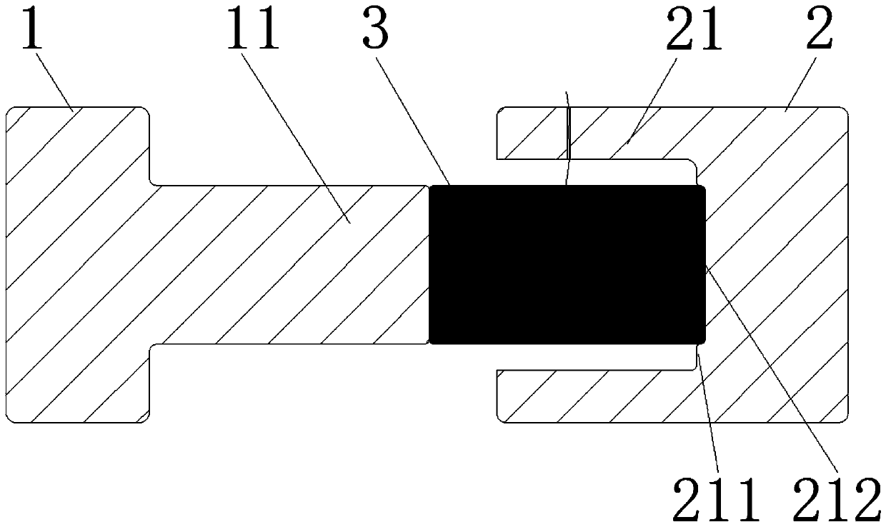
[0032] A pipe extrusion die for a Gleeble thermal simulation testing machine, including a left mold 1 and a right mold 2, one end of the left mold 1 is connected to the mechanical transmission pressure head of the Gleeble thermal simulation testing machine, and the size of the connecting end of the left mold is The same size as the mechanical transmission indenter, one end surface of the right mold 2 is connected with the bearing indenter of the Gleeble thermal simulation testing machine and the size of the connecting end of the right mold is the same as that of the bearing indenter.

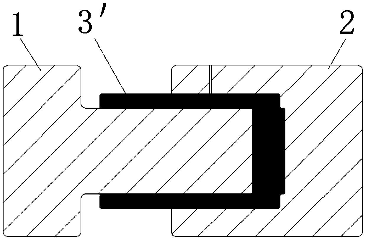
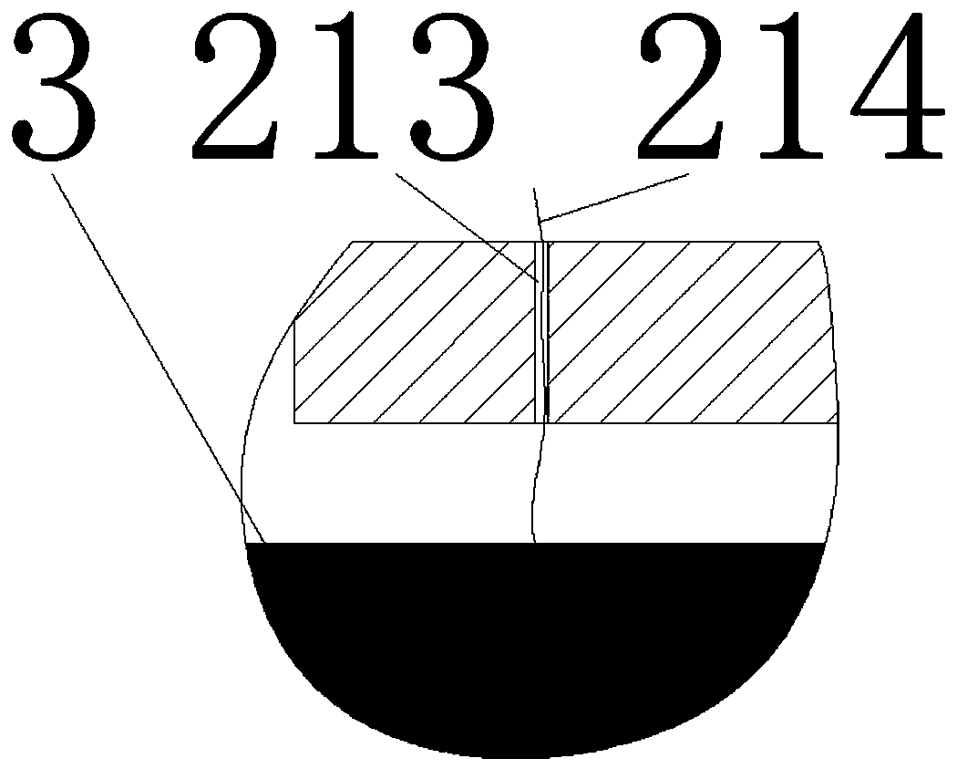
[0033] On the basis of the above structure, such as Figure 1-3 As shown, the other end surface of the left mold 1 is fixed with a cylindrical left mold lug 11, and the other end surface of the right mold 2 is provided with a hollow cylinder that matches the left mold lug 11. The extrusion concave cavity 21, and the diameter of the extrusion concave cavity 21 is greater than the diameter of the ...

Embodiment 2

[0037] On the basis of the structure of the pipe extrusion die of a Gleeble thermal simulation testing machine disclosed in Example 1, further technical improvements are made. The specific improved structure is as follows:

[0038] The position of the positioning groove 212 is set at the center position of the side surface 211 where it is located in the extrusion cavity 21 . In this way, the extruded sample 3 is conveniently snapped into the positioning groove to play a positioning role, and at the same time, the sample is ensured to be in the middle of the extruded cavity 21 . In addition, the diameter of the positioning groove 212 is the same as that of the extrusion sample 3 .

[0039]Simultaneously, in order to ensure the accuracy of extrusion, it is also ensured that the size of the left die bump 11 is the same as that of the extrusion sample 3 .

Embodiment 3

[0041] On the basis of the structure of a pipe extrusion die of a Gleeble thermal simulation testing machine disclosed in Example 2, further technical improvements are made. The specific improved structure is as follows:

[0042] On the other end face of the left mold 1, a detachable cylindrical left mold lug 11 is arranged. Because the inner diameter of the extruded pipe material 3' is the same as the diameter of the left die bump 11. Therefore, the inner diameter of the extruded pipe material 3 ′ can be determined by changing the diameter of the left mold block 11 . In this way, pipes of various specifications can be extruded conveniently.


PUM

PropertyMeasurementUnit
Hole diameteraaaaaaaaaa
Diameteraaaaaaaaaa
Heightaaaaaaaaaa

Abstract

The invention discloses a Gleeble thermal simulated test machine pipe extrusion mold and a use method thereof. The Gleeble thermal simulated test machine pipe extrusion mold comprises a left mold anda right mold, one end face of the left mold is connected with a mechanical transmission press head, one end face of the right mold is connected with a force bearing press head, the other end face of the left mold is provided with a left mold convex block, the other end face of the right mold is provided with a hollow extrusion concave cavity which is matched with the left mold convex block, a positioning groove is formed in the extrusion concave cavity, a through hole is formed in the extrusion concave cavity, a thermocouple is mounted in the through hole, one end of the thermocouple is connected with an extrusion sample, and the other end of the thermocouple is connected with a temperature control system of a Gleeble test machine. The Gleeble thermal simulated test machine is applied to simulate pipe extrusion, through cooling and heating of different speeds and extrusion deforming of different speeds, meanwhile, changes of parameters such as temperature, force, strain and stress in the test extrusion process are recorded, and the pipe extrusion new process parameters can be rapidly explored.

Description

technical field [0001] The invention belongs to the technical field of material processing, and in particular relates to a pipe extrusion die of a Gleeble thermal simulation testing machine and a use method thereof. Background technique [0002] Most parts are formed by die casting or extrusion, and for some tubing, extrusion is the most suitable forming method. With the development of my country's industry and the advancement of science and technology, people's requirements for the quality of extruded pipes are also getting higher and higher. Therefore, extrusion process parameters, pipe microstructure and mechanical properties have a crucial impact on the quality of extrusion products. [0003] In the past, for the extrusion of new pipes, a large number of experiments were needed to explore the optimal process parameters, which greatly affected the development cycle and production efficiency of new products. In order to avoid material waste, seek reasonable extrusion pro...

Claims


Application Information

Patent Timeline
IPC IPC(8): B21C23/08B21C25/02B21C31/00
CPCB21C23/085B21C25/025B21C31/00
Inventor 李玉贵宋耀辉王顺李华英赵广辉刘二强
Owner TAIYUAN UNIVERSITY OF SCIENCE AND TECHNOLOGY
Learn More