Radar level meter

A radar level gauge and support plate technology, which is applied in liquid/fluid solid measurement, engine lubrication, electric vehicles, etc., can solve the problems affecting the accuracy of radar level gauge measurement results, loss of radar level gauge, and lack of protective structures. and other problems, to achieve the effect of convenient installation and disassembly, delaying rust, and avoiding sun exposure

Inactive Publication Date: 2020-04-03
陕西诺盈自动化仪表有限公司
View PDF3 Cites 1 Cited by
  • Summary
  • Abstract
  • Description
  • Claims
  • Application Information

AI Technical Summary

Problems solved by technology

However, most of the radar level gauges in the above-mentioned patents are exposed and lack protective structures, and the radar level gauges are exposed to wind and sun for a long time, which will wear out the radar level gauges and affect the accuracy of the measurement results of the radar level gauges. The radar level gauge will be eaten by small animals like mice, or small birds will excrete feces on the radar level gauge, polluting the instrument

Method used


Image

  • Radar level meter
  • Radar level meter
  • Radar level meter

Examples


Embodiment 1

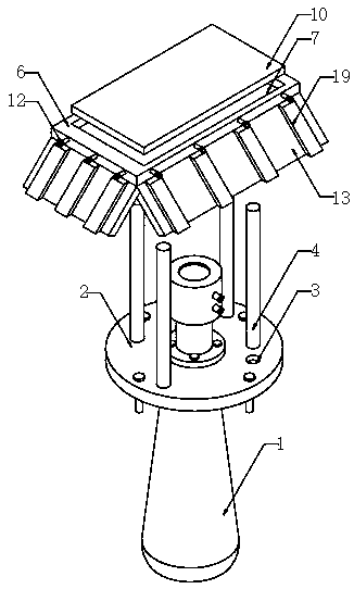
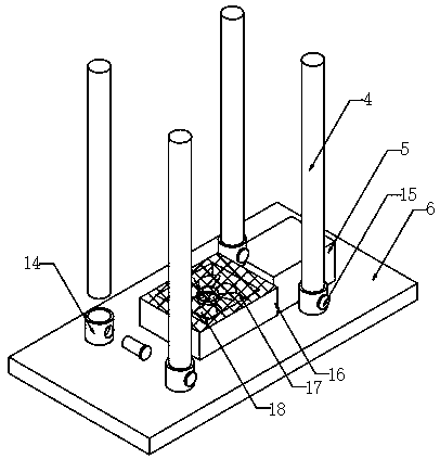
[0023] Such as Figure 1-Figure 3 As shown, a radar level gauge includes a radar level gauge body 1, a mounting flange 2 is fixed in the middle of the radar level gauge body 1, and a plurality of mounting holes 3 are opened on the top of the mounting flange 2, and a plurality of The mounting holes 3 are threadedly connected to the bottoms of the corresponding vertical rods 4 respectively, and the tops of a plurality of vertical rods 4 are engaged with the corresponding sleeves 14 respectively. The top of the tube 14 is fixedly connected to the four corners of the bottom end of the support plate 6 respectively, the vertical rod 4 is screwed into the inside of the mounting hole 3, the sleeve 14 at the bottom end of the support plate 6 is aligned with the vertical rod 4 and then put down, so that the vertical rod 4 The rod 4 is snapped into the sleeve 14, and then inserted into the pin shaft 15 to complete the installation of the support plate 6. The operation is simple and conve...

Embodiment 2

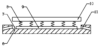
[0025] On the basis of Embodiment 1, such as figure 1 with figure 2 As shown, the protective structure includes a groove 7 set in the middle of the top of the support plate 6, the middle of the top of the groove 7 is fixedly provided with a boss 9, and the top of the boss 9 is fixed with a plurality of compression springs 8, and the plurality of compression springs The tops of 8 are fixedly connected with the bottom of the top plate 10. When a foreign object falls on the top plate 10, the top plate 10 is impacted and falls, and squeezes the compression spring 8. The compression spring 8 compresses the top plate 10 in the process of restoring deformation. Jacking up can bounce foreign matter away to avoid accumulation on the top plate 10 and cause excessive pressure on the top plate 10. The top of the support plate 6 is provided with a plurality of drainage chutes 11, and one end of the drainage chute 11 is fixedly communicated with the groove 7 , the other end of the drain c...

Embodiment 3

[0027] On the basis of embodiment one and embodiment two, such as figure 1 with image 3 As shown, light baffles 13 are fixedly installed on the edge of the support plate 6, and a plurality of solar photovoltaic panels 19 are fixedly installed on one side of the four light baffles 13. The light baffles 13 can block sunlight and avoid radar level gauges. The main body 1 is exposed to the sun, while the solar photovoltaic panel 19 absorbs solar energy and converts it into electrical energy. The middle part of the bottom end of the support plate 6 is fixed with a fan base 16, and the middle part of the bottom end of the fan base 16 is provided with a mounting groove 17. The inside of the mounting groove 17 is fixed and installed There is a fan 18, and the bottom of the fan base 16 is fixedly provided with a protective screen. On the one hand, the wind blown by the fan 18 can clean the surface of the radar level gauge body 1, sweep the dust on the radar level gauge body 1, and pre...


PUM


Abstract

The invention discloses a radar level meter. The radar level meter comprises a radar level meter body, a mounting flange is fixedly arranged in the middle of the radar level meter body; a plurality ofmounting holes are formed in the top end of the mounting flange; the plurality of mounting holes are respectively in threaded connection with the bottoms of the corresponding vertical rods; the topsof the plurality of vertical rods are respectively connected with the corresponding sleeves in a clamping manner; the top ends of the four sleeves are fixedly connected with the bottom end of a supporting plate. A protection structure is arranged at the top of the supporting plate. By arranging the mounting holes, the vertical rods, the supporting plates and the sleeves, the vertical rods can be screwed into the mounting holes; by arranging the supporting plate, the boss, the compression spring, the top plate, a drainage chute and a drainage pipe, when foreign matter falls onto the top plate to extrude a compression spring, the compression spring jacks up the top plate, the foreign matter can be bounced off, and rapid drainage can be achieved in rainy days.

Description

technical field [0001] The invention relates to a radar level gauge, in particular to a radar level gauge. Background technique [0002] The radar level meter adopts the measurement method of microwave pulse, and it can be normal in the industrial frequency band range, and the beam energy is low. Perform non-contact continuous measurements. It is suitable for occasions where dust, temperature and pressure change greatly, and inert gas and steam exist. The radar level meter has no harm to the human body and the environment, and has the advantages of not being affected by the specific gravity of the medium, not being affected by the change of the dielectric constant, and not requiring on-site calibration. [0003] In view of this, Chinese Patent No. CN105157789B proposes a radar level gauge for high-precision measurement. The application of analog circuits completes the process of converting high-speed signals to low-speed by repeating multiple cycles, that is, converting hi...

Claims


Application Information

Patent Timeline
IPC IPC(8): G01F23/284H02J7/35
CPCG01F23/284H02J7/35
Inventor 李敏
Owner 陕西诺盈自动化仪表有限公司
Why Eureka
Try Eureka