
Short-wave time difference positioning method based on ionized layer information

A technology of time difference positioning and ionosphere, which is applied in the field of passive detection, can solve problems such as ionosphere environmental impact, increase system complexity and cost, and achieve the effect of expanding business scope, no need to build stations, and simple equipment

Inactive Publication Date: 2020-04-03
中国电波传播研究所
View PDF2 Cites 11 Cited by
  • Summary
  • Abstract
  • Description
  • Claims
  • Application Information

AI Technical Summary

Problems solved by technology

The least square method and the total least square method need to add an additional receiving station to convert the nonlinear equation system into a linear equation system, but these algorithms increase the complexity and cost of the system
[0007] The application of the conventional time difference positioning method is mainly applicable to the field of line-of-sight detection or ground wave beyond-the-horizon detection, while the long-distance and large-scale reconnaissance and monitoring target positioning based on the propagation of short-wave signals reflected by the ionosphere, the time difference positioning technology faces more difficulties: One is the precise time difference extraction technology; the other is the impact of the ionospheric environment

Method used


Image

  • Short-wave time difference positioning method based on ionized layer information
  • Short-wave time difference positioning method based on ionized layer information
  • Short-wave time difference positioning method based on ionized layer information

Examples


Embodiment 1

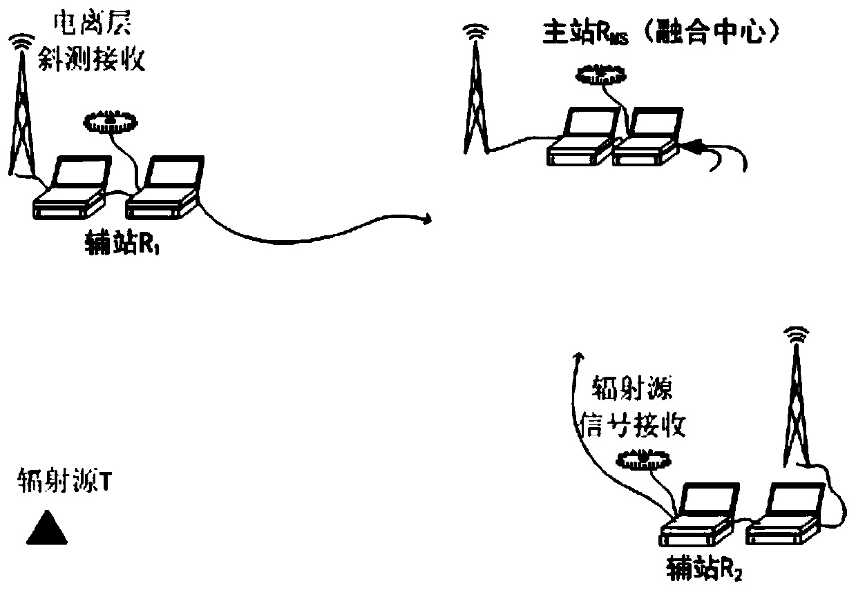
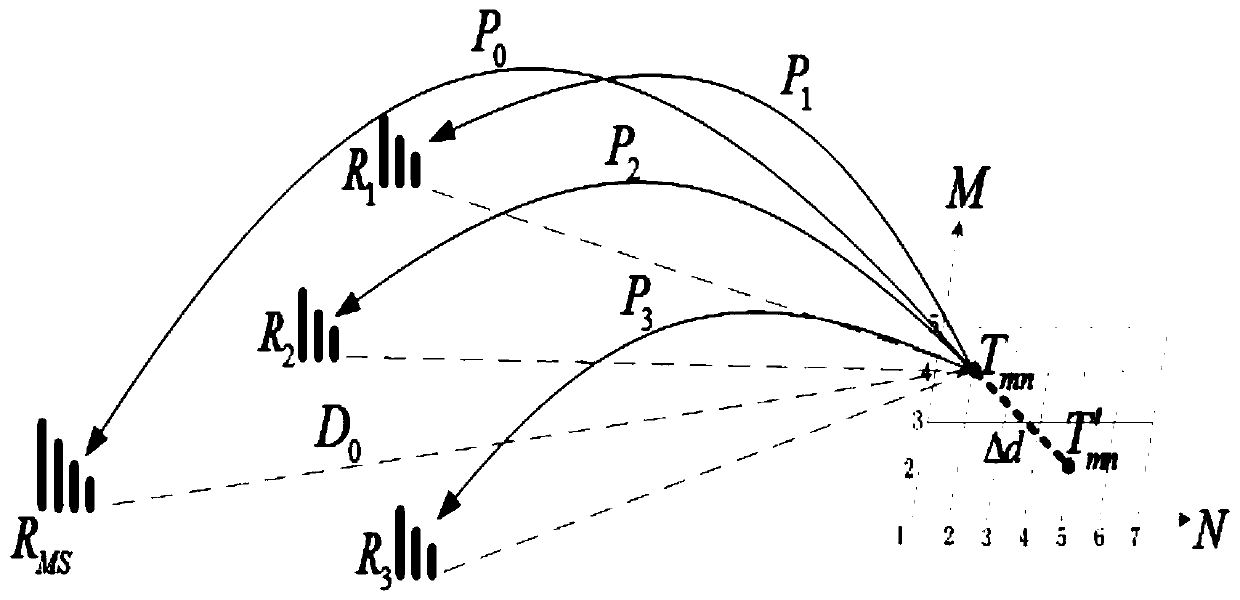
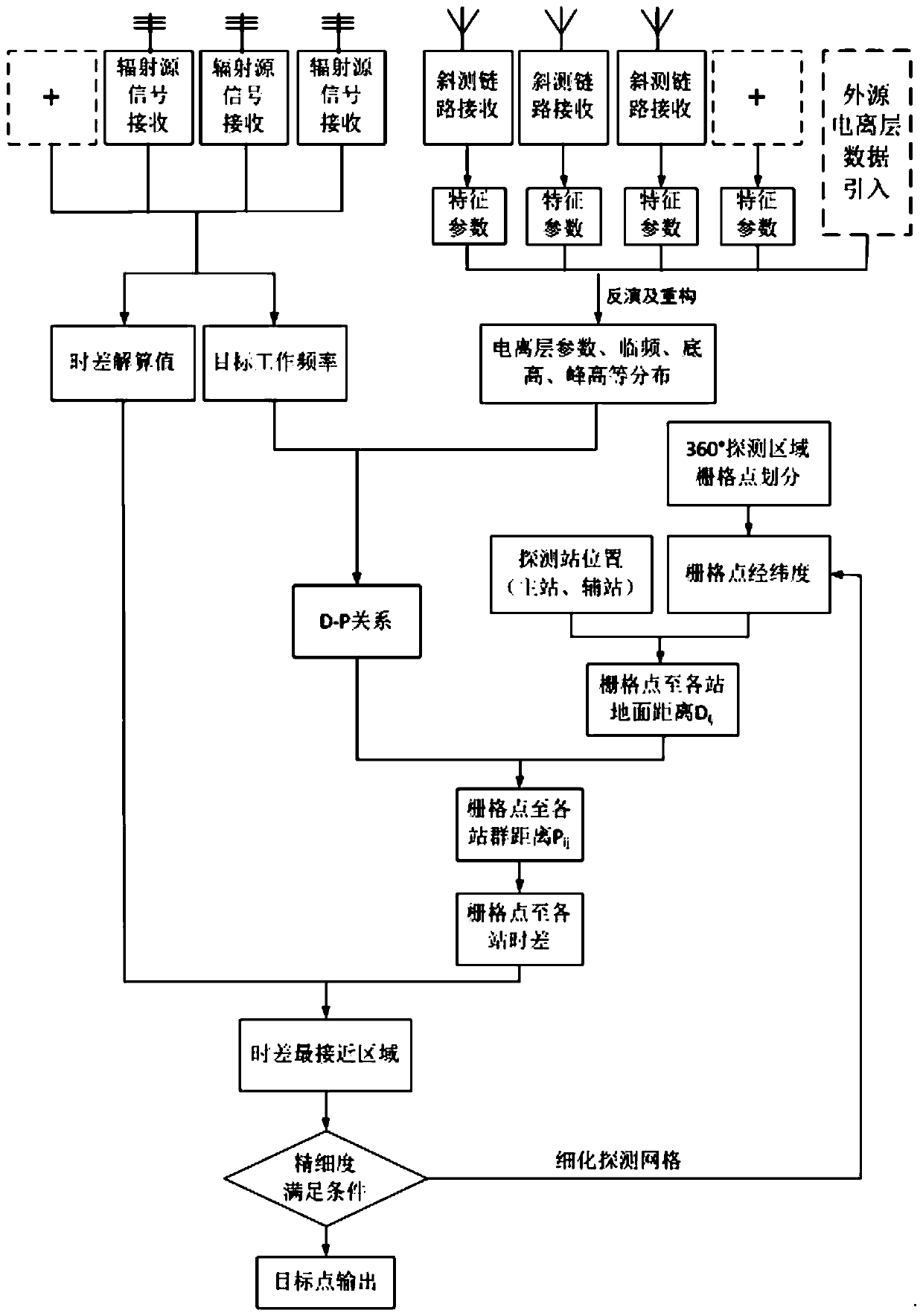
[0056] Embodiment 1, with Qingdao as the main station, recorded as No. 0, Beijing, Xinxiang, and Suzhou as auxiliary stations, respectively recorded as No. 1, No. 2, and No. 3 stations, the time difference positioning of the radiation source located in Xi'an is carried out, and the process is as follows image 3 shown, including the following steps:

[0057] Step 1, determine the site distribution:

[0058] Select the station with the strongest average signal strength as the main station, that is, the fusion center; conduct a preliminary search to determine the orientation of the radiation source, and then select the auxiliary station according to the orientation, so that the auxiliary station is located in the fan-shaped area where the fusion center points to the orientation of the radiation source;

[0059] Step 2, radio wave environmental data acquisition:

[0060] Step 21, ionospheric oblique measurement link reception:

[0061] The ionospheric oblique measurement receiv...


PUM


Abstract

The invention discloses a short-wave time difference positioning method based on ionospheric information. The method comprises the following steps of 1, determining the station distribution; 2, acquiring the electric wave environment data; 3, acquiring the signal time difference extraction data of the receiving stations; 4, performing ionospheric parameter inversion and regional ionospheric reconstruction; 5, positioning the time difference. The method is based on a signal source positioning method based on time difference of arrival (TDOA), the passive positioning can be realized by only analyzing the time difference of the radiation signals arriving at the receiving stations without depending on an array antenna, and the method is a positioning method which is simple in equipment, convenient in networking and being able to guarantee higher precision, and has a wide application prospect in short-wave passive positioning, especially in vehicle-mounted and ship-borne reconnaissance systems.

Description

technical field [0001] The invention belongs to the field of passive detection, in particular to an ionospheric reflection-based trans-horizon short-wave time-difference positioning method in the field. Background technique [0002] Compared with active positioning, passive positioning technology has the advantages of good concealment, long range, large coverage and strong survivability because it does not transmit signals to the target. It is more and more widely used in modern military and civilian fields. There are two main passive positioning technologies commonly used, one is to use a single stationary platform or a moving platform to perform fixed-point positioning or dynamic positioning for the target's continuous direction finding; the other is to use multiple platforms to measure the signal arrival angle or signal arrival time difference at the same time To locate the target, it is called cross-location. The cross positioning method is divided into the angular cros...

Claims


Application Information

Patent Timeline
Patent Type & Authority Applications(China)
IPC IPC(8): G01S5/06
CPCG01S5/06
Inventor 田德元王世凯高荣山杨龙泉
Owner 中国电波传播研究所
Learn More