Built-in multidirectional adjusting type craniocerebral drainage device

A multi-directional adjustment and drainage technology, which is applied to suction devices, drug devices, hypodermic injection devices, etc., can solve the problem of poor grip between the puncture flexible tube and the inner core steel needle, and the inability to adjust the direction and angle of the puncture tube. , The direction and angle of the hose cannot be adjusted, so as to avoid damage to important functional areas, reduce postoperative edema, and reduce the effect of hematoma mass

Pending Publication Date: 2020-04-07
朱金磊
View PDF0 Cites 4 Cited by
  • Summary
  • Abstract
  • Description
  • Claims
  • Application Information

AI Technical Summary

Problems solved by technology

There are currently two types of craniocerebral drainage devices on the market. Among them, the disposable minimally invasive craniocerebral drainage set (soft channel) has poor grip when the puncture tube and the inner core steel needle are used, and the puncture tube is squeezed. Pressure deformation, discount, blockage, the inner core steel needle pierces the brain tissue by mistake through the hole of the hose, and the direction and angle of the hose cannot be adjusted after the inner core steel needle is withdrawn; the disposable minimally invasive craniocerebral drainage set (hard channel) The scope of use is limited when used, and the drainage effect is good only for intracranial hematoma. When used at the same time, bleeding in the puncture channel is easy to occur, and positioning is difficult. The direction and angle of the puncture tube cannot be adjusted, and the drainage effect is not ideal.

Method used


Image

  • Built-in multidirectional adjusting type craniocerebral drainage device
  • Built-in multidirectional adjusting type craniocerebral drainage device
  • Built-in multidirectional adjusting type craniocerebral drainage device

Examples


Embodiment 1

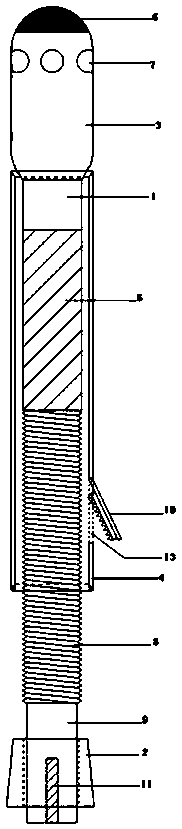
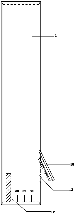
[0019] This embodiment provides a built-in multi-adjustable brain drainage device, which is composed of a drainage tube, a fixer, a valve and a drainage bag connected in sequence. figure 1 Shown is a drainage tube, which consists of a tube body 1 and a soft plug 2 detachably connected to the tail of the tube body, wherein the tube body is composed of a coaxial and freely detachable inner tube 3 and an outer tube 4 .

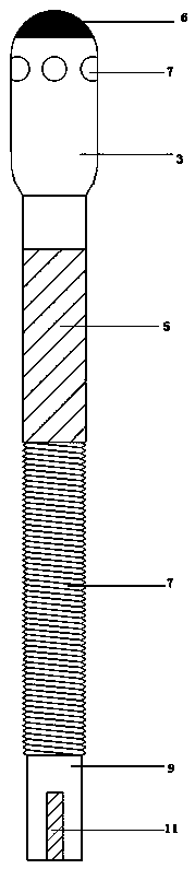
[0020] Such as image 3 As shown, the inner tube 3 is a circular tube whose top end is closed into a dome shape, and the middle section of the inner tube 3 is a pre-plastic structure 5. When the inner tube 3 extends out of the outer tube, the pre-plastic part is automatically bent into an angle of 90°, which becomes Figure 4 structure shown.

[0021] Such as figure 1 , figure 2 As shown, the front end of the inner tube 3 with the preplastic structure 5 is enlarged, and the diameter of the expanded section is the same as that of the outer tube 4; the top of t...


PUM


Abstract

The invention discloses a built-in multidirectional adjusting type craniocerebral drainage device. The drainage device is composed of a drainage tube, a fixator, a valve and a drainage bag. A tube body of the drainage tube is composed of an inner tube and an outer tube, which are coaxial and can be freely detached; the middle section of the inner tube has a pre-plastic structure; the top end of the inner tube is provided with an under-ray developing coating; a side opening is formed in the upper half section of the inner tube; threads are arranged at the tail end of the inner tube; an annularsoft plug sleeves the tail end of the inner tube and can be tightly clamped between the tube walls of the inner tube and the outer tube; elastic buckles are arranged on the outer tube wall, and open holes are formed in the corresponding positions; and marks are arranged at the tail end of the inner tube, and angle scale marks are arranged at the tail end of the outer tube, so that the rotation direction of the inner tube is controlled thereby. The drainage device can be combined with CT to flexibly adjust the direction within the effective radius range to conduct accurate positioning drainageon hematoma or hydrops and hydrops. By the device, the first suction rate of intracranial hematoma is increased, the mass effect of hematoma and postoperative encephaledema are reduced, intracranial pressure can be rapidly reduced, and accurate and effective target treatment is achieved.

Description

technical field [0001] The invention relates to the field of medical devices, in particular to a built-in multidirectional adjustable brain drainage device. Background technique [0002] Craniocerebral drainage devices appeared in our country in the 1970s. After 2000, various self-made or medical device manufacturers gradually appeared and widely used in clinical practice. At present, neurosurgery is developing in the direction of minimally invasive operations. Brain drainage devices are often used in cerebral hemorrhage, hydrocephalus, and brain tumor operations. Its function is to quickly reduce intracranial pressure, drain bloody cerebrospinal fluid, and inject drugs into the brain. Wide range of uses. There are currently two types of craniocerebral drainage devices on the market. Among them, the disposable minimally invasive craniocerebral drainage set (soft channel) has poor grip when the puncture tube and the inner core steel needle are used, and the puncture tube is ...

Claims


Application Information

Patent Timeline
Patent Type & Authority Applications(China)
IPC IPC(8): A61M1/00A61M25/02
CPCA61M1/0023A61M25/02A61M2025/0253A61M2210/0687A61M2210/0693A61M1/84A61M2210/005
Inventor 朱金磊贾慧珍
Owner 朱金磊
Why Eureka
Try Eureka