
Environment-friendly waste gas treatment device

A waste gas treatment device, an environmentally friendly technology, applied in the direction of gas treatment, combined devices, membrane technology, etc., can solve the problems of building waste gas treatment devices, achieve the effect of improving speed and efficiency, and wide applicability

Pending Publication Date: 2020-04-07
珠海京工检测技术有限公司 +1
View PDF0 Cites 1 Cited by
  • Summary
  • Abstract
  • Description
  • Claims
  • Application Information

AI Technical Summary

Problems solved by technology

[0003] Aiming at the problem of different waste gas discharge and treatment, the factory cannot build different waste gas treatment devices for different waste gas types due to production cost problems, and provides an environmentally friendly waste gas treatment device

Method used


Image

  • Environment-friendly waste gas treatment device
  • Environment-friendly waste gas treatment device
  • Environment-friendly waste gas treatment device

Examples


Embodiment 1

[0031] Treatment methods for organic industrial waste gas

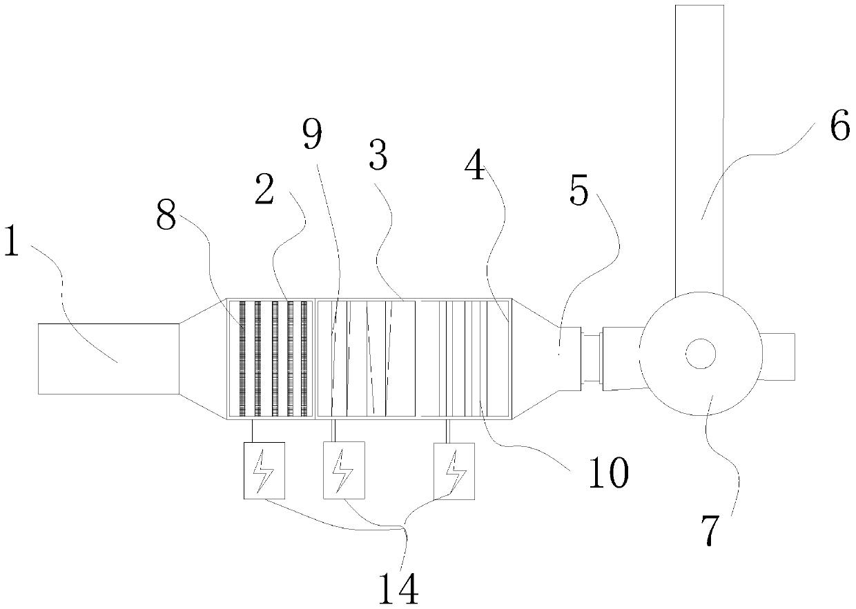
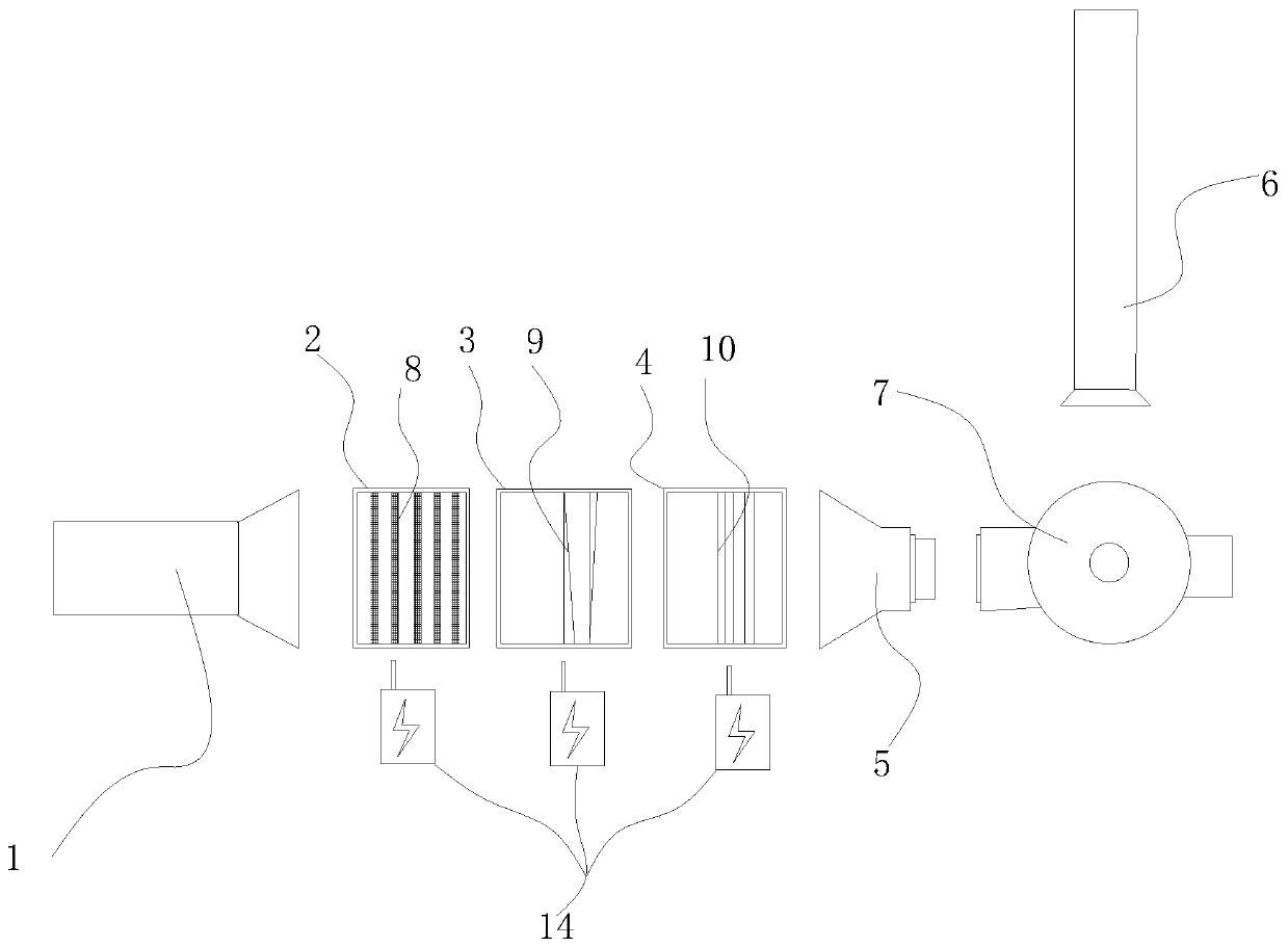
[0032] Open the door of each treatment box, and the adsorbate filling box 8, heating lamp tube 9 and uv light tube 10 are respectively arranged on the horizontal rails in the first treatment box 2, the second treatment box 3 and the third treatment box 4.

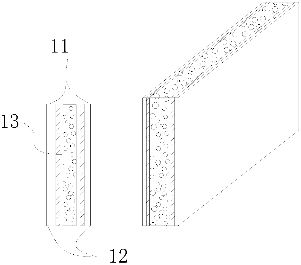
[0033] Wherein the adsorbate filling box 8 has a three-layer structure, which is respectively a filter fabric layer 11, a filter screen 12 and a sponge-filled activated carbon filling layer 13.

[0034] The second processing box 3 and the third processing box 4 are provided with a relay box 14

[0035] The heating lamp tube 9 and the uv light tube 10 are connected to the relay box 14 on the second treatment box 3 and the third treatment box 4 respectively.

[0036] The industrial waste gas is introduced, and the exhaust fan 7 is turned on. Under the directional action of the exhaust fan 7, the exhaust gas enters the first treatment box 2, and the adsorbate filling...

Embodiment 2

[0041] Treatment methods for oil fume and fire smoke exhaust gas

[0042] Open the doors of each treatment box, and set the adsorbate filling box 8, heating lamp tube 9 and adsorbate filling box 8 on the horizontal rails in the first treatment box 2, the second treatment box 3 and the third treatment box 4 respectively.

[0043] The adsorbate filling box 8 has a three-layer structure, which is an organic polymer composite fabric layer 11 with high oil absorption performance, a filter screen 12 and a filling layer 13 added with hydrophobic perlite, ceramsite and coke.

[0044] The second processing box 3 is provided with a relay box 14

[0045] The heating lamp tube 9 is connected to the relay box 14 on the second processing box 3 .

[0046] Feed oily smoke and fire smoke waste gas, turn on the exhaust fan 7, and the exhaust gas enters the first treatment box 2 under the directional action of the exhaust fan 7, and the adsorbate filling box 8 provided in the first treatment bo...


PUM


Abstract

The invention provides an environment-friendly waste gas treatment device simple in structure and convenient in operation. The environment-friendly waste gas treatment device comprises a gas inlet pipeline, a first treatment box, a second treatment box, a third treatment box, a gas outlet pipeline, a chimney, an adsorbate filling box, a heating lamp tube and a UV light tube; each treatment box canbe independently opened, the types of required adsorbents or filtering membranes in the treatment boxes can be selected and replaced according to different waste gas types, the applicability is wide,a three-section type design is adopted, three different waste gas treatment methods can be opened and closed according to needs to be combined for use, and the treatment effect is better. Various treatment modes are matched for use, so that the treated waste gas type range is wide; and a plurality of composite inert catalysts are prepared according to different waste gas components, so that the waste gas treatment speed and efficiency are greatly improved.

Description

technical field [0001] The invention relates to waste gas treatment technology, in particular to an environment-friendly waste gas treatment device. Background technique [0002] Air pollution is one of the most prominent environmental problems in the world at present. The main source of its pollutants is industrial waste gas. Due to different production processes, industrial waste gas produces different types of pollutants. Different types of pollutants should adopt different treatment processes. Waste gas generally adopts water film dust removal + activated carbon adsorption method or dry filter dust removal + activated carbon adsorption method, and comes from the acid and alkali discharged in the process of chemical industry, electronics, metallurgy, electroplating, textile (chemical fiber), food, machinery manufacturing and other industries. Waste gas is generally taken from sources: acid and alkaline waste gas discharged in the process of chemical industry, electronics,...

Claims


Application Information

Patent Timeline
IPC IPC(8): B01D53/75B01D50/00
CPCB01D50/00B01D53/005B01D53/007B01D53/75B01D2251/104B01D2259/804
Inventor 王磊欧阳珊唐丽萍吴钟静蔡阳伦林楚宏
Owner 珠海京工检测技术有限公司
Learn More