Active electro-hydraulic coupling steering system and vehicle

A technology of steering system and electric power steering, which is applied in the direction of electric steering mechanism, mechanical steering gear, fluid steering mechanism, etc. It can solve the problems of large size of steering motor, unfavorable assembly and use, and large power torque carried by electric power assist, so as to save space , the effect of using space

Active Publication Date: 2020-04-07
ZHENGZHOU YUTONG BUS CO LTD
View PDF10 Cites 4 Cited by
  • Summary
  • Abstract
  • Description
  • Claims
  • Application Information

AI Technical Summary

Problems solved by technology

[0005] The purpose of the present invention is to provide an active electro-hydraulic coupling steering system and a vehicle, which are used to solve the problem that the existing active electro-hydraulic coupling power steering adopts a variable transmission ratio and then couples the power boost output, resulting in a large power boost torque carried by the electric power booster, resulting in steering failure. The size of the motor is too large to make reasonable use of the vehicle space, which is not conducive to the problem of assembly and use
[0006] In order to achieve vehicle steering coupling and active steering control, solve the problem of poor control accuracy caused by the existing active electro-hydraulic coupling power steering using first variable transmission ratio and then coupling power output

Method used


Image

  • Active electro-hydraulic coupling steering system and vehicle
  • Active electro-hydraulic coupling steering system and vehicle
  • Active electro-hydraulic coupling steering system and vehicle

Examples


Embodiment Construction

[0024] The present invention will be described in further detail below in conjunction with the accompanying drawings.

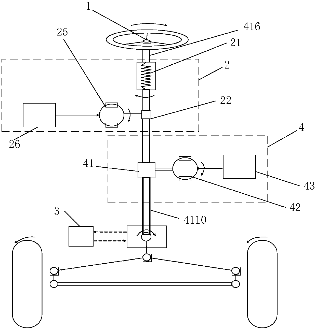
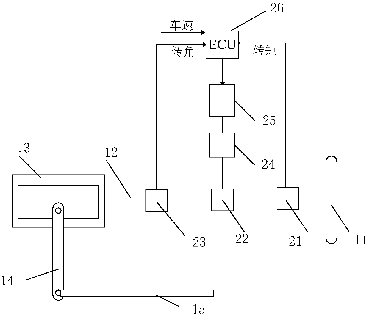
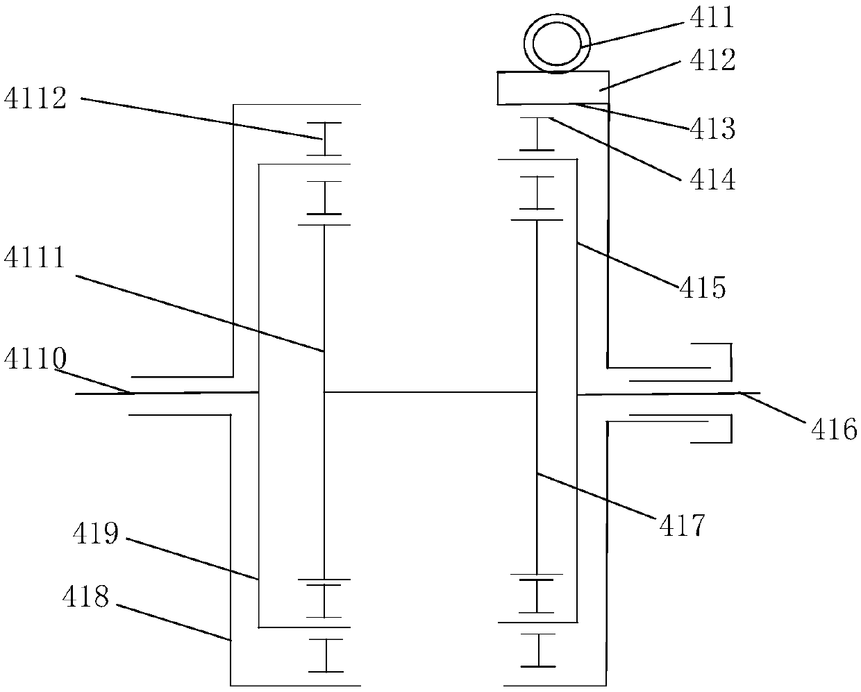
[0025] The present invention provides an active electro-hydraulic coupling steering system, such as Figure 1 to Figure 4 As shown, the steering system includes a mechanical steering mechanism 1, an electric power steering mechanism 2, a transmission ratio mechanism 4 and a hydraulic power steering mechanism 3; wherein the mechanical steering mechanism 1 includes a steering input shaft 416 for connecting the steering wheel 11 and a steering input shaft for The steering output shaft 4110 that drives the vehicle to turn; the steering input shaft 416 and the steering output shaft 4110 together constitute the steering shaft 12, the steering input shaft 416 is connected to the input end of the variable transmission ratio mechanism 4, and the output end of the variable transmission ratio mechanism 4 is connected to the steering output shaft 4110 ; the output end of...


PUM


Abstract

The invention relates to the technical field of vehicle steering control, in particular to an active electro-hydraulic coupling steering system and a vehicle. The steering system comprises a mechanical steering mechanism, an electric power steering mechanism, a variable transmission ratio mechanism and a hydraulic power steering mechanism. The mechanical steering mechanism comprises a steering input shaft connected with a steering wheel and a steering output shaft used for driving a vehicle to turn. The steering input shaft is connected with the input end of the variable transmission ratio mechanism. The output end of the variable transmission ratio mechanism is connected with the steering output shaft. The output end of the electric power steering mechanism is in transmission connection with the steering input shaft. The output end of the hydraulic power steering mechanism is in transmission connection with the steering output shaft. The electric power steering mechanism is arranged between the steering wheel and the variable transmission ratio mechanism. The assisting power borne by the electric power steering mechanism is the ratio of the steering aligning torque to the steeringtransmission ratio, and becomes smaller through the filtering of the variable transmission ratio, such that the assisting power borne by the electric power steering mechanism is reduced. Thus, the size of equipment in the electric power steering mechanism does not need to be designed to be very large, and space can be effectively saved.

Description

technical field [0001] The invention relates to the technical field of vehicle steering control, in particular to an active electro-hydraulic coupling steering system and a vehicle. Background technique [0002] Passenger cars generally use hydraulic power steering systems. With the rapid development of passenger car intelligent technology, unmanned driving technology and intelligent driving assistance technology, as the two major technical directions of passenger car intelligence, have put forward new requirements for the passenger car steering system. Since the hydraulic power steering system cannot realize the active steering function; and the application of the electric power steering system needs to consider the load power of the motor, therefore, the design of the electro-hydraulic coupling steering system and the corresponding control method applied to the bus has very important practical significance. [0003] Active steering is the constant change of the transmissio...

Claims


Application Information

Patent Timeline
Patent Type & Authority Applications(China)
IPC IPC(8): B62D5/04B62D5/06B62D3/04
CPCB62D5/04B62D5/06B62D3/04
Inventor 丁金全郭耀华王长新
Owner ZHENGZHOU YUTONG BUS CO LTD
Why Eureka
Try Eureka