
Cutting device for glass processing

A cutting and glass technology, used in glass cutting devices, glass manufacturing equipment, manufacturing tools, etc., can solve the problems of labor-intensive, slow production, and inability to meet the needs of use.

Inactive Publication Date: 2020-04-07
闫凤杰
View PDF13 Cites 8 Cited by
  • Summary
  • Abstract
  • Description
  • Claims
  • Application Information

AI Technical Summary

Problems solved by technology

[0002] Glass is actually a kind of prestressed glass. In order to improve the strength of glass, chemical or physical methods are usually used to form compressive stress on the surface of the glass. When the glass is subjected to external forces, the surface stress is first offset, thereby improving the bearing capacity and enhancing the wind resistance of the glass itself. Pressure resistance, cold and heat resistance, impact resistance, etc., in the processing of glass, it is necessary to carry out batch processing of certain shapes and glass of different specifications, and it is necessary to cut out the set specifications after measuring the glass, and cut the glass Most of them are cut by manpower, and the cutting speed is slow. The existing glass cutting and production are all done by hand, and at the same time, two people are required to carry the glass together, which consumes a lot of manpower, slow production speed, low efficiency, and cannot meet people's needs. Use requirements, poor security

Method used


Image

  • Cutting device for glass processing
  • Cutting device for glass processing
  • Cutting device for glass processing

Examples


Embodiment Construction

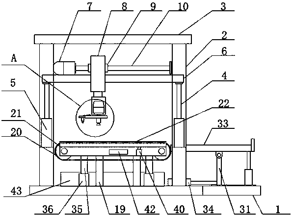
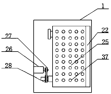
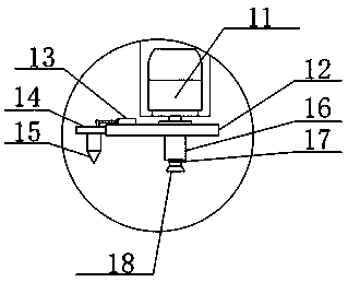
[0022] The following will clearly and completely describe the technical solutions in the embodiments of the present invention with reference to the accompanying drawings in the embodiments of the present invention. Obviously, the described embodiments are only some, not all, embodiments of the present invention. Based on the embodiments of the present invention, all other embodiments obtained by persons of ordinary skill in the art without making creative efforts belong to the protection scope of the present invention. see Figure 1-7 , the present invention provides a technical solution: a cutting device for glass processing, including a base 1, a pillar 2, and a top plate 3 fixedly connected by welding, and a first cylinder 4 and a second cylinder are respectively arranged inside the pillar 2 5. The first cylinder 4 and the second cylinder 5 are set to push the lifting rod 6 to move up and down. There is a chute 24 on the inner side of the pillar 2. The chute 24 is set to pr...


PUM


Abstract

The invention particularly relates to a cutting device for glass processing. The device comprises a base, supporting columns and a top plate. A first air cylinder and a second air cylinder are arranged in the supporting columns. An asynchronous motor is arranged on a left side of an upper end of a lifting rod; a sliding sleeve is arranged on the sliding rod; a moving cylinder is mounted on a frontend surface of the sliding sleeve; a first belt pulley is mounted on a left side of a rotating roller rotating shaft; a second belt pulley is mounted on a rotating shaft of a rotating motor; a bottomplate is arranged on a right side of the base; and an auxiliary air cylinder is arranged at an upper end of a joint of the bottom plate and the base. A sliding plate is arranged at an upper end of the bottom plate; and a machined part placing plate is horizontally arranged at top ends of a supporting rod and a first supporting air cylinder. A fixed plate drives a glass cutter to rotate through adriving motor, and the rotating roller plays a supporting role, so that the glass is cut, the glass is convenient to cut, the glass is sucked through a suction cup to move up and down after cutting iscompleted, a redundant part is separated from round glass, and the use requirements of people can be met.

Description

technical field [0001] The invention belongs to the technical field of glass processing, and in particular relates to a cutting device for glass processing. Background technique [0002] Glass is actually a kind of prestressed glass. In order to increase the strength of glass, chemical or physical methods are usually used to form compressive stress on the surface of the glass. When the glass is subjected to external forces, the surface stress is first offset, thereby improving the bearing capacity and enhancing the wind resistance of the glass itself. Pressure resistance, cold and heat resistance, impact resistance, etc., in the processing of glass, it is necessary to carry out batch processing of certain shapes and glass of different specifications, and it is necessary to cut out the set specifications after measuring the glass, and cut the glass Most of them are cut by manpower, and the cutting speed is slow. The existing glass cutting and production are all done manually....

Claims


Application Information

Patent Timeline
IPC IPC(8): C03B33/03
CPCC03B33/03
Inventor 闫凤杰李晓静
Owner 闫凤杰
Learn More