
Milling machine and control method of milling machine

A milling machine and milling technology, which is applied in the control of milling machines and in the field of milling machines, can solve problems such as smashing people and vehicles around, spilling waste materials, and misoperation, so as to ensure the output position of materials and realize automatic control , Guarantee the effect of construction safety

Inactive Publication Date: 2020-04-07
SANY AUTOMOBILE MFG CO LTD
View PDF5 Cites 2 Cited by
  • Summary
  • Abstract
  • Description
  • Claims
  • Application Information

AI Technical Summary

Problems solved by technology

Therefore, construction workers have a high construction intensity, and even misuse, causing waste materials to spill and hit surrounding personnel and vehicles.
Especially for small milling machines with rear feeding, the material truck is behind the operator. During operation, the construction personnel must often observe the position of the material truck and the distribution of waste in the hopper backwards, which is extremely inconvenient.
[0003] In related technologies, the milling machine has the ability to measure the milling depth, width, feeding speed, and driving speed, and has the ability to calculate the amount of feeding, but it does not detect the position and speed of the feeding car and the distribution of materials in the hopper. Realize automatic feeding

Method used


Image

  • Milling machine and control method of milling machine
  • Milling machine and control method of milling machine
  • Milling machine and control method of milling machine

Examples


Embodiment 1

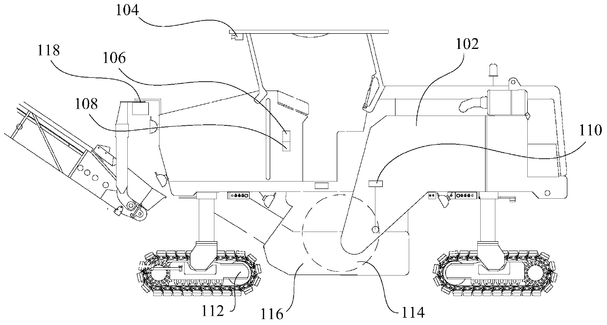
[0052] like figure 1 As shown, the first embodiment of the present invention provides a milling machine, including: a body 102 , a feeding device, an image processing device and a main controller 108 .

[0053] Among them, the milling machine is used in conjunction with the feeding car, the milling machine is used for milling the ground, and the materials generated by the milling are transported to the feeding car through the feeding device, and the feeding car is used for conveying the materials.

[0054] The image processing device can obtain the position of the feeding cart, and judge the relative speed of the feeding cart and the milling machine according to the position change of the feeding cart, and the image processing device can also obtain the cross-sectional size of the hopper of the feeding cart.

[0055] The main controller 108 is electrically connected with the image processing device. After obtaining the cross-sectional size of the hopper, the main controller 10...

Embodiment 2

[0064] like figure 1As shown, the second embodiment of the present invention provides a milling machine, including: a body 102 , a feeding device, an image processing device, a detection device and a main controller 108 .

[0065] Among them, the milling machine is used in conjunction with the feeding car, the milling machine is used for milling the ground, and the materials generated by the milling are transported to the feeding car through the feeding device, and the feeding car is used for conveying the materials.

[0066] The image processing device can obtain the position of the feeding cart, and judge the relative speed of the feeding cart and the milling machine according to the position change of the feeding cart, and the image processing device can also obtain the cross-sectional size of the hopper of the feeding cart.

[0067] The main controller 108 is electrically connected with the image processing device. After obtaining the cross-sectional size of the hopper, th...

Embodiment 3

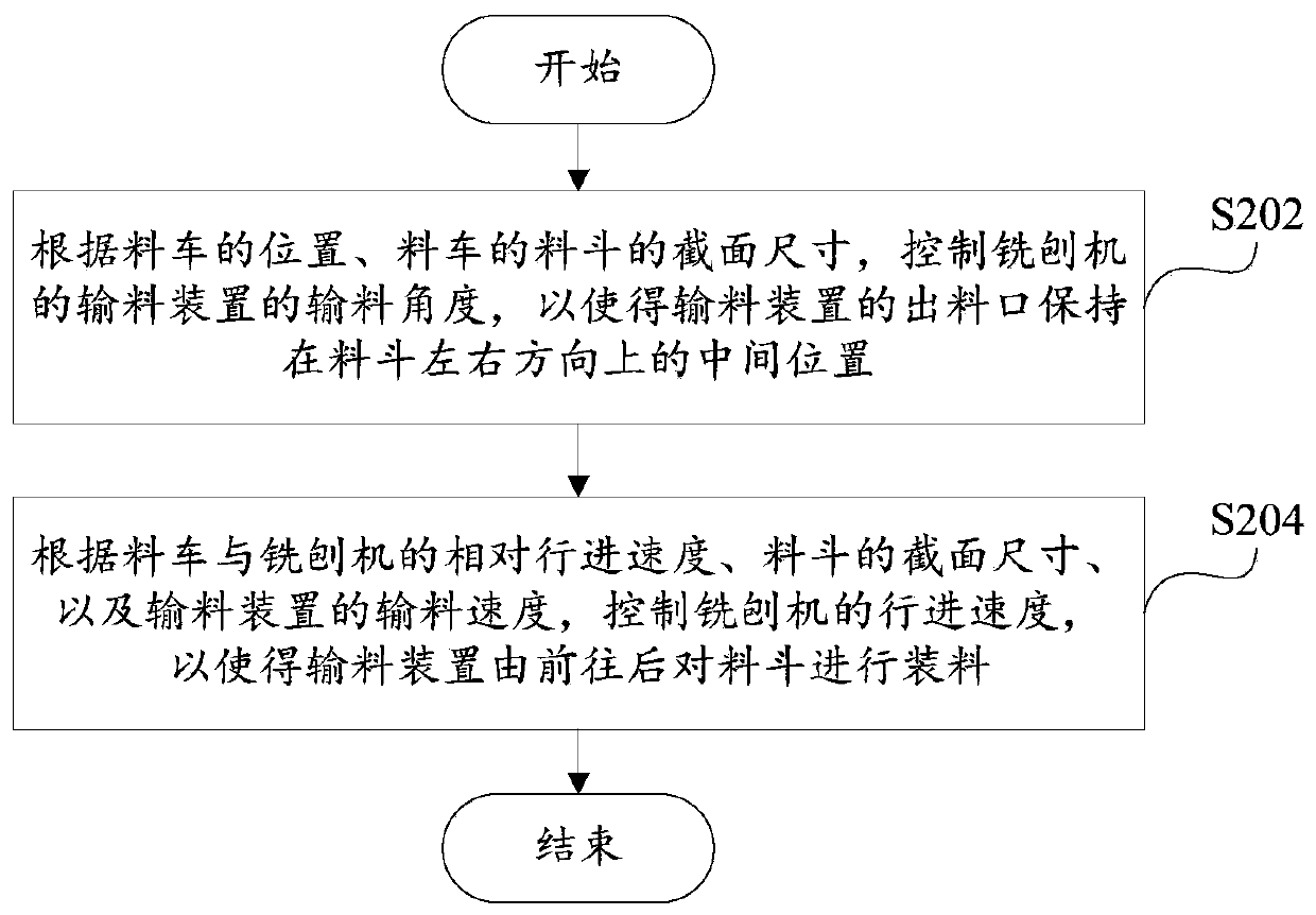
[0075] figure 2 It is a schematic flowchart of a control method of a milling machine according to an embodiment of the present invention, such as figure 2 As shown, the control method of the milling machine includes:

[0076] Step 202, according to the position of the feeding car and the cross-sectional size of the hopper of the feeding car, control the feeding angle of the feeding device of the milling machine, so that the outlet of the feeding device is kept at the middle position in the left and right direction of the hopper;

[0077] Step 204, according to the relative traveling speed of the feeding car and the milling machine, the cross-sectional size of the hopper, and the feeding speed of the feeding device, control the traveling speed of the milling machine, so that the feeding device can load the hopper from front to back .

[0078] The control method of the milling machine proposed in this embodiment firstly obtains the position of the feeding car and the cross-s...


PUM


Abstract

The invention provides a milling machine and a control method of the milling machine, and the milling machine comprises a machine body; a material conveying device movably arranged on the machine body; an image processing device arranged on the machine body, and an image processing device configured to obtain the position of a skip car, wherein the section size of a hopper of the skip car and therelative advancing speed of the skip car and the milling machine; a master controller arranged on the machine body and electrically connected with the image processing device; a main controller whichis configured to control the conveying angle of the conveying device according to the position of the skip car and the section size of a hopper. Materials discharged from a discharge port of the conveying device fall into the middle of the hopper in the width direction. The advancing speed of the milling machine is controlled according to the relative advancing speed of the skip car and the milling machine, the section size of the hopper and the conveying speed of the conveying device, so that the conveying device charges the hopper from front to back, the milling machine provided by the invention can realize automatic control, and the working intensity of operators is reduced.

Description

technical field [0001] The invention relates to the field of engineering machinery, in particular to a milling machine and a control method for the milling machine. Background technique [0002] The main function of the milling machine is to mill the damaged road surface and transport the waste generated by milling to the feeder. During the construction process, most of the operations of the construction personnel are to adjust the conveying materials, such as controlling the distribution of waste in the feed truck, controlling the distance between the milling machine and the feed truck, avoiding collisions, and so on. Therefore, construction workers have a high construction intensity, and even misuse, causing waste materials to spill and hit surrounding personnel and vehicles. Especially for the small milling machine with rear feeding, the feed truck is behind the operator. During operation, the construction personnel must often observe the position of the feed truck and t...

Claims


Application Information

Patent Timeline
Patent Type & Authority Applications(China)
IPC IPC(8): E01C23/088
CPCE01C23/088G05D1/0246E01C19/004
Inventor 吴绪成冯细见王李
Owner SANY AUTOMOBILE MFG CO LTD
Learn More