Rotor structure of permanent magnet auxiliary type bearingless synchronous reluctance motor

A synchronous reluctance motor, rotor structure technology, applied in the magnetic circuit shape/style/structure, synchronous machine, synchronous machine parts and other directions, can solve the problems of large torque and suspension force pulsation, reduce torque and suspension Effects of force pulsation, reduced workload, high torque density

Active Publication Date: 2020-04-07
扬中市检验检测中心
View PDF7 Cites 6 Cited by
  • Summary
  • Abstract
  • Description
  • Claims
  • Application Information

AI Technical Summary

Problems solved by technology

[0005] The purpose of the present invention is to propose a rotor structure of a permanent magnet assisted bearingless synchronous reluctance motor to solve the problem that the existing permanent magnet assisted bearingless synchronous reluctance motor has large torque and suspension force pulsation during operation , improve the motor control precision, so as to realize the stable suspension and high-efficiency operation of the motor rotor, and better apply to the electric drive system

Method used


Image

  • Rotor structure of permanent magnet auxiliary type bearingless synchronous reluctance motor
  • Rotor structure of permanent magnet auxiliary type bearingless synchronous reluctance motor
  • Rotor structure of permanent magnet auxiliary type bearingless synchronous reluctance motor

Examples


Embodiment Construction

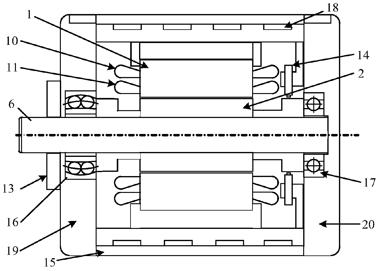
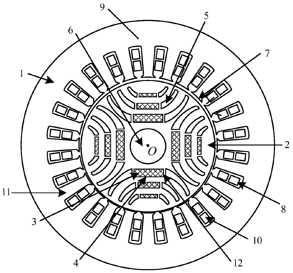
[0022] see figure 1 The permanent magnet assisted bearingless synchronous reluctance motor includes a stator 1, a rotor 2 and a rotating shaft 6. The rotor 2 is coaxially located inside the stator 1. The center of the rotor 2 is coaxially sleeved with a rotating shaft 6. A slot is opened in the center of the rotor 2 for placement. Spindle 6. The stator 1 has double-layer windings, the outer winding is the torque winding 10 , and the inner winding is the suspension force winding 11 . There is an air gap between the inner wall of the stator 1 and the outer wall of the rotor 2, and the thickness of the air gap is related to the power level of the motor, the selected permanent magnet material, and the processing and assembly process of the stator 1 and rotor 2. The casing 15 is used for fixing the stator 1 , the left end cover 19 and the right end cover 20 , the left end cover 19 is used for fixing the self-aligning ball bearing 14 , and the right end cover 20 is used for fixing ...


PUM


Abstract

The invention discloses a rotor structure of a permanent magnet auxiliary type bearingless synchronous reluctance motor. Four groups of magnetic barriers are uniformly and symmetrically arranged on the rotor structure in the circumferential direction; each group of magnetic barriers is divided into an inner layer, a middle layer and an outer layer from inside to outside; each layer of magnetic barrier comprises a rectangular permanent magnet mounting groove, two magnetic isolation bridges which are symmetrically distributed relative to the center line of the diameter direction of the permanentmagnet mounting groove, and two rib parts which are arranged between the permanent magnet mounting groove and the magnetic isolation bridges; a permanent magnet is fixedly embedded into the permanentmagnet mounting groove in each layer of magnetic barrier; the radial contour line of each magnetism isolating bridge comprises a magnetism isolating bridge outer boundary line, a magnetism isolatingbridge inner boundary line and a magnetism isolating bridge end part; and the two ends of the end of the magnetic isolation bridge are connected with the outer boundary line of the magnetic isolationbridge and the inner boundary line of the magnetic isolation bridge respectively, the outer boundary line of the magnetic isolation bridge, the inner boundary line of the magnetic isolation bridge andthe middle line of the magnetic isolation bridge are quadratic function curve segments, the end of the magnetic isolation bridge is composed of two Bezier cubic curves, and torque and suspension force pulsation are effectively reduced.

Description

technical field [0001] The invention belongs to the field of motor manufacturing and control, and relates to a permanent magnet assisted bearingless synchronous reluctance motor, in particular to a rotor structure of a permanent magnet assisted bearingless synchronous reluctance motor capable of reducing torque and suspension force pulsation. Background technique [0002] Bearingless motor is a kind of AC motor with novel and unique structure and principle. The suspension force winding with pole logarithm difference of 1 is stacked in the stator torque winding. Electromagnetic torque can be generated at the same time by controlling the current flowing into the two sets of windings. and radial suspension force. Synchronous reluctance motor has the advantages of fast dynamic response, simple structure and low cost, and has received more and more attention in industrial applications. The bearingless synchronous reluctance motor has the advantages of both magnetic bearings and ...

Claims


Application Information

Patent Timeline
Patent Type & Authority Applications(China)
IPC IPC(8): H02K1/27H02K21/02H02K29/03
CPCH02K1/2766H02K21/028H02K29/03H02K2213/03
Inventor 朱熀秋高敏
Owner 扬中市检验检测中心
Why Eureka
Try Eureka