Supercharge Your Innovation With Domain-Expert AI Agents!

An intelligent multi-mode power factor correction method and circuit for a switching power supply

A power factor correction and switching power supply technology, applied in the field of power supply, can solve the problems of low efficiency, failure to meet the design requirements of high power density, wide input voltage range power supply, complex control methods, etc., and achieve the effect of cost reduction

Active Publication Date: 2020-12-15
DONGGUAN SHILONG FUHUA ELECTRONICS
View PDF9 Cites 0 Cited by
  • Summary
  • Abstract
  • Description
  • Claims
  • Application Information

AI Technical Summary

Problems solved by technology

[0010] The CCM mode is suitable for high-power applications. Its advantages are small peak value of inductor current and small volume of magnetic components; disadvantages are large reverse recovery loss of boost freewheeling diode, low efficiency and complicated control method
[0011] The BCM mode is suitable for use in small and medium power applications. Its advantages are that the switching frequency is not fixed, the EMC is good, and the control method is relatively simple; the disadvantage is that the peak value of the inductor current is large, and the PFC inductor is large.
[0012] The DCM mode is suitable for use in small and medium power applications. Its advantage is that the input current waveform naturally follows the input voltage waveform, and the control method is simple; the disadvantage is that the peak value of the inductor current is large, and the PFC inductor is large.
[0013] To sum up, it can be seen that the existing traditional analog IC single-mode power factor correction circuits have different shortcomings, and none of them can meet the power supply design requirements of high power density and wide input voltage range.
[0014] The active PFC circuit built with hardware is relatively complicated, and the hardware cost accounts for nearly 20% of the total cost of the switching power supply

Method used


Image

  • An intelligent multi-mode power factor correction method and circuit for a switching power supply
  • An intelligent multi-mode power factor correction method and circuit for a switching power supply
  • An intelligent multi-mode power factor correction method and circuit for a switching power supply

Examples


Embodiment Construction

[0044] The technical solution of the present invention will be further described below in conjunction with the accompanying drawings and through the best implementation mode.

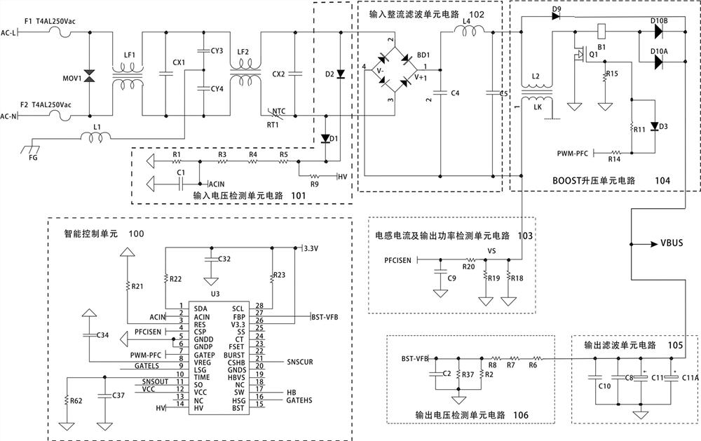
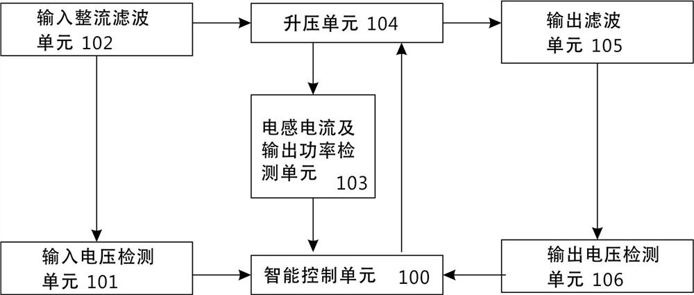
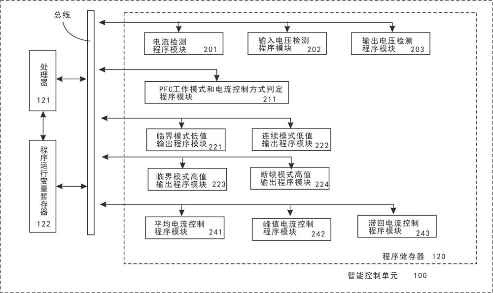
[0045] like Figure 1~4 As shown, the implementation of switching power supply intelligent multi-mode power factor correction method, the method includes:

[0046] The first step, first set the input voltage detection unit circuit 101 in the AC power input circuit of the switching power supply, connect the input rectification filter unit circuit 102 after the AC power input circuit, then the BOOST boost unit circuit 104, and then connect the BOOST boost unit circuit A sampling winding LK is added to the boost inductor L2 in the circuit 104; the sampling winding LK is connected to the inductance current and the output power detection unit circuit 103, and an intelligent control unit 100 is additionally set in the switching power supply, and the input voltage detection unit circuit 101 has an output detec...


PUM


Abstract

The invention discloses an intelligent multi-mode power factor correction method and circuit for a switching power supply, and the circuit comprises an intelligent control unit and an input voltage detection unit circuit; a BOOST unit circuit is disposed behind a rectification filtering unit circuit, and a sampling winding LK is added to a boost inductor L2. The LK is connected with an inductive current and output power detection unit. The input end, with the internal ADC function, of a microprocessor U3 detects the input voltage, output voltage and inductive current. The circuit overcomes thedefects that an existing power factor correction circuit is single in mode and cannot meet the requirement of a high-power miniaturized medical power supply. Program design is carried out through theapplication of the microprocessor, and the intelligent switching of three modes of the PFC-BOOST circuit is realized, so the advantages are complementary, and the circuit meets the requirements of American six-level energy efficiency, European Union COC V5 tier2, high power density of 0.65 W / cm<3> and wide voltage range of input AC80V-AC264V, and the cost is reduced by 10% due to the reduction ofthe volume of the magnetic device.

Description

technical field [0001] The invention relates to the technical field of power supplies, in particular to an intelligent multi-mode power factor correction method and circuit for a switching power supply. Background technique [0002] The power factor of the power supply is represented by PFC (PFC, Power Factor Correction). The higher the PFC, the higher the energy conversion efficiency. [0003] PFC is divided into passive PFC and active PFC. Passive PFC uses inductance compensation to reduce the phase difference between the input fundamental current and voltage, and passive PFC can only achieve 70% to 80%. [0004] The active PFC in the prior art is composed of multiple operational amplifiers and inductance-capacitance devices. It samples the voltage and current and drives the switch tube to turn on or off the input current in a timely manner, so that it can be synchronized with the voltage as much as possible. The PFC can achieve more than 90% . Therefore, the energy con...

Claims


Application Information

Patent Timeline
Patent Type & Authority Patents(China)
IPC IPC(8): H02M1/42
CPCH02M1/4225Y02B70/10
Inventor 黄子田
Owner DONGGUAN SHILONG FUHUA ELECTRONICS
Features
  • R&D
  • Intellectual Property
  • Life Sciences
  • Materials
  • Tech Scout
  • Unparalleled Data Quality
  • Higher Quality Content
  • 60% Fewer Hallucinations
Learn More