Dust removal equipment for wall top cutting

A technology of dust removal equipment and cutting discs, which is applied in stone processing equipment, liquid separation agent, and dispersed particle separation, etc., can solve the problems of ineffective dust reduction and difficult collection of waste water, and achieve the effect of easy cleaning and reduced dust content

Active Publication Date: 2020-04-10
聊城市龙泰激光设备有限公司
View PDF10 Cites 1 Cited by
  • Summary
  • Abstract
  • Description
  • Claims
  • Application Information

AI Technical Summary

Problems solved by technology

[0005] In order to overcome the shortcomings of not being able to effectively reduce dust and difficult to collect waste water, the technical problem is to provide a dust removal equipment for wall top cutting that can effectively reduce dust and collect waste water easily

Method used


Image

  • Dust removal equipment for wall top cutting
  • Dust removal equipment for wall top cutting

Examples


Embodiment 1

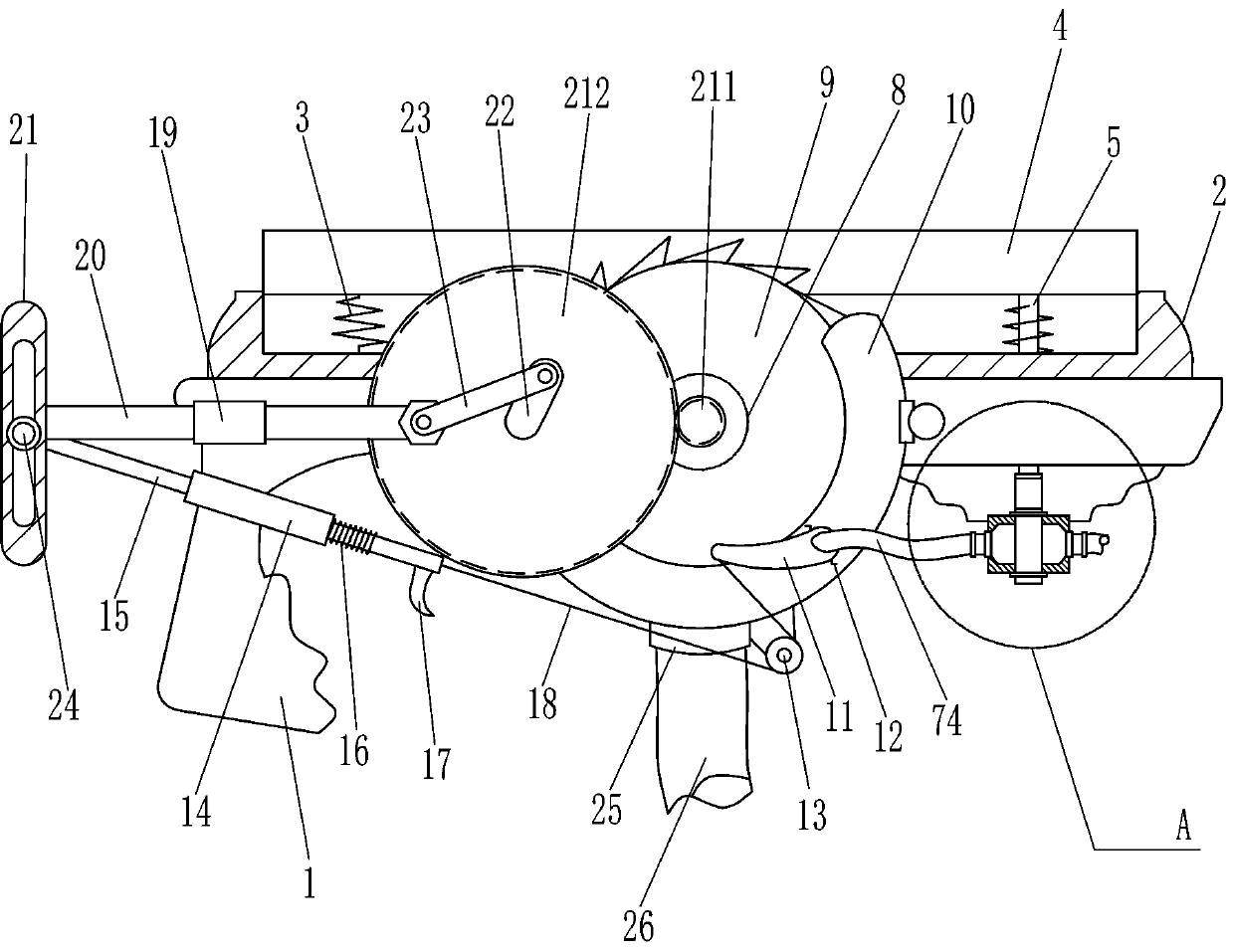
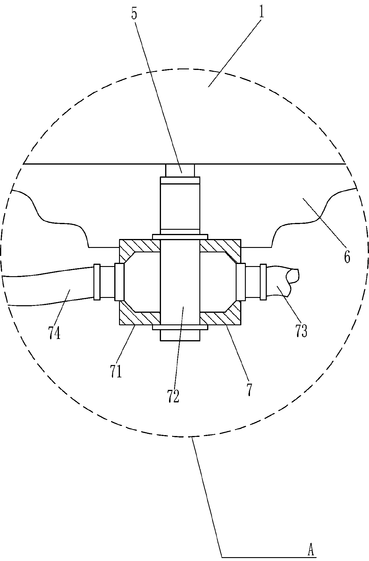
[0018] A dust removal equipment for wall top cutting, such as Figure 1-2 As shown, it includes grip plate 1, concave plate 2, first compression spring 3, transparent plate 4, moving rod 5, mounting plate 6, liquid inlet device 7, motor 8, cutting disc 9, safety cover 10, liquid spray Head 11, torsion spring 12, fixed pulley 13, first guide sleeve 14, first guide rod 15, second compression spring 16, push rod 17 and backguy 18, handle plate 1 top is provided with concave plate 2, concave plate 2. The left and right sides of the inner bottom are connected with the first compression spring 3, the top of the first compression spring 3 is provided with a transparent plate 4, and the right side of the bottom of the transparent plate 4 is connected with a moving rod 5, and the moving rod 5 is connected with the concave plate 2 and the grip in turn. The plate 1 is connected in a sliding manner, the bottom right side of the grip plate 1 is provided with a mounting plate 6, the front s...

Embodiment 2

[0022] On the basis of Example 1, such as figure 1 As shown, it also includes a second guide sleeve 19, a second guide rod 20, a guide sleeve 21, a first gear 211, a second gear 212, a first connecting rod 22, a second connecting rod 23 and a sliding sleeve 24, and the cutting disc 9 The front side is provided with a first gear 211, the left part of the safety cover 10 is rotatably connected with a second gear 212, the second gear 212 meshes with the first gear 211, and the left front side of the grip plate 1 is provided with a second guide sleeve 19, A second guide rod 20 is slidably connected in the second guide sleeve 19, and a guide sleeve 21 is provided at the left end of the second guide rod 20, and a sliding sleeve 24 is slidably connected in the guide sleeve 21. Connect, the right end of the second guide rod 20 is rotatably connected with the second connecting rod 23, the right end of the second connecting rod 23 is rotatably connected with the first connecting rod 22,...

Embodiment 3

[0025] On the basis of Example 2, such as figure 1 As shown, it also includes a filter cover 25 and a drain pipe 26. The bottom of the safety cover 10 is provided with a filter cover 25, and the filter cover 25 is connected with a drain pipe 26.

[0026] Through the cooperation of the filter cover 25 and the drain pipe 26, the waste water in the safety cover 10 can be filtered, and the sand particles are left in the filter cover 25 to facilitate subsequent cleaning and collection, and the waste water is discharged to the collection area through the drain pipe 26. It avoids the waste water from dripping directly on the ground, which makes subsequent cleaning inconvenient, and achieves the effect of easy cleaning.


PUM


Abstract

The invention relates to dust removal equipment, in particular to dust removal equipment for wall top cutting. The technical problem of the invention is how to provide dust removal equipment for walltop cutting that can effectively reduce dust and facilitate the collection of waste water. The dust removal equipment for wall top cutting comprises a holding plate, a concave plate and the like, wherein the concave plate is arranged at the top part of the holding plate. According to the dust removal equipment, a transparent plate is used, workers can observe the working condition of the equipmenton the other side, thus dust can be prevented from drifting into the eyes of workers, and protection measures are provided for the workers; water is sprayed to the surface of a cutting disc, thus thedust content can be effectively reduced, and a good working environment is provided for the workers; through cooperation of a filtering cover and a liquid discharging pipe, waste water in a safety cover can be filtered, sand grains are left in the filtering cover, subsequent cleaning and collecting are facilitated, the waste water is discharged to a collecting region by means of the liquid discharging pipe, so as to avoid the situation that subsequent cleaning is inconvenient because the waste water directly drips on the ground, and the effect of easy cleaning is achieved.

Description

technical field [0001] The invention relates to a dust removal device, in particular to a dust removal device for wall top cutting. Background technique [0002] In building decoration, due to many factors, workers need to carry out secondary decoration on the already decorated wall top. In this process, in order to facilitate the division of decoration areas, it is necessary to cut the wall top and divide the decoration for the decoration workers. area. [0003] When using traditional cutting tools to cut the top of the wall, due to the lack of good dust removal equipment, the working space is full of dust, which is very difficult for workers to work normally, and it is easy to cause workers to suffer from pneumoconiosis if accumulated for a long time. The method of dust, because water will seep into the wall and cause damage to the wall, is unacceptable by homeowners and difficult to use on a large scale. [0004] How to design a kind of dust removal equipment for wall t...

Claims


Application Information

Patent Timeline
IPC IPC(8): B28D1/04B28D7/02B01D47/06
CPCB01D47/06B28D1/04B28D7/02
Inventor 龙健
Owner 聊城市龙泰激光设备有限公司
Why Eureka
Try Eureka