
An energy-saving traction device applied to river vessel traction

A traction device and energy-saving technology, applied in the field of energy-saving traction devices, can solve the problems of small scope of application, high operating cost, air pollution, etc., and achieve the effects of saving energy consumption, large scope of application, and good environmental protection effect.

Active Publication Date: 2020-12-08
童波
View PDF7 Cites 0 Cited by
  • Summary
  • Abstract
  • Description
  • Claims
  • Application Information

AI Technical Summary

Problems solved by technology

[0004] The purpose of the present invention is to provide an energy-saving traction device applied to the traction of river vessels, which solves the problem that the existing energy-saving traction devices for traction of river vessels are basically powered by burning diesel oil, which will generate a large amount of exhaust gas during use. It causes air pollution, consumes a lot of energy, has high operating costs, does not have energy-saving and environmental protection effects, and the traction device needs to be manually controlled throughout the process. Each traction device can only be used for ships with a fixed tonnage, and the scope of application is small.

Method used


Image

  • An energy-saving traction device applied to river vessel traction
  • An energy-saving traction device applied to river vessel traction
  • An energy-saving traction device applied to river vessel traction

Examples


Embodiment Construction

[0031] The technical solutions of the present invention will be described below in conjunction with examples, as will be described, as described herein, only the embodiments of the invention, not all embodiments. Based on the embodiments in the present invention, those of ordinary skill in the art will belong to the scope of the present invention without all other embodiments obtained in the preparation of creative labor.

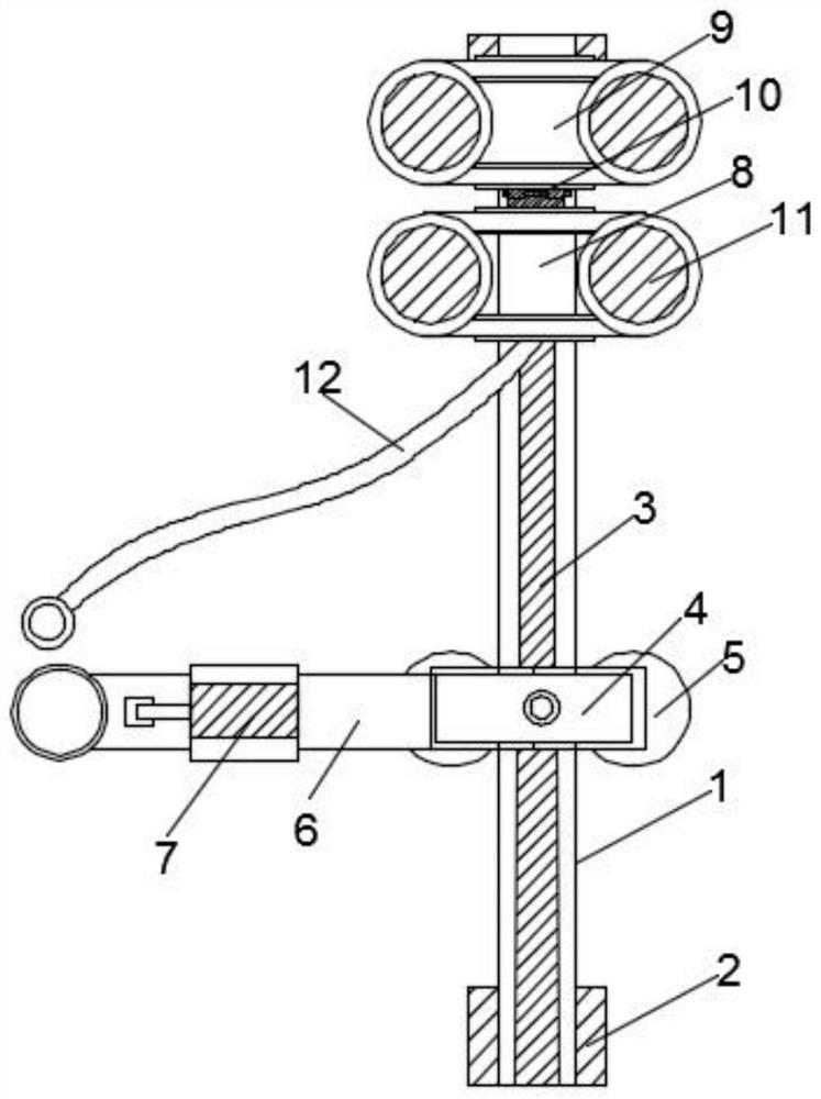
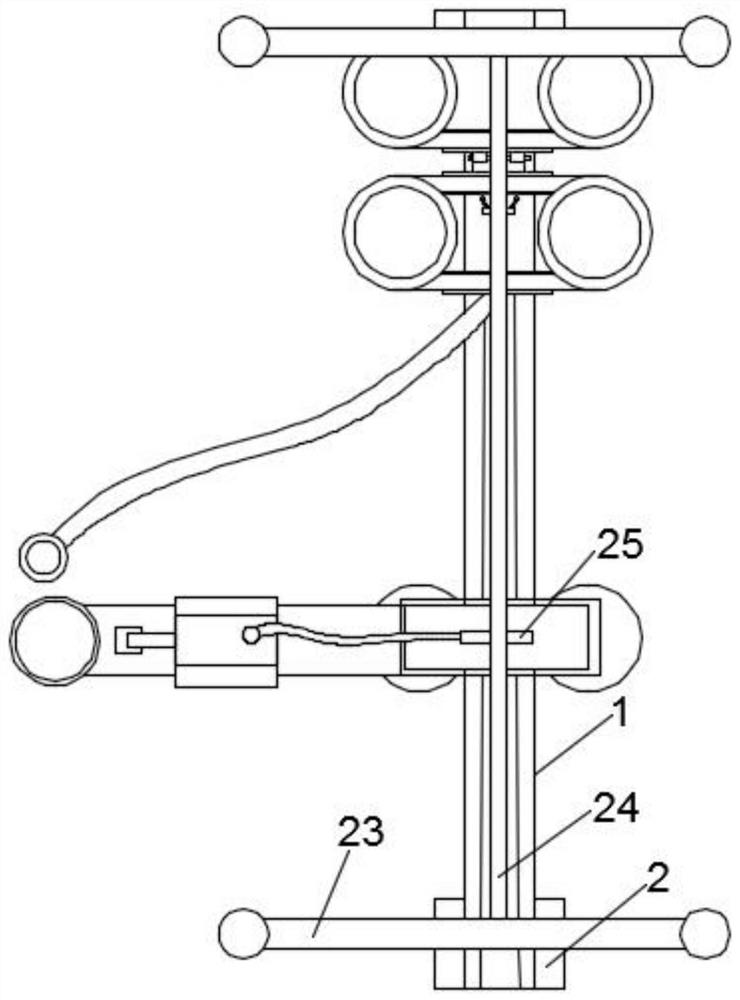
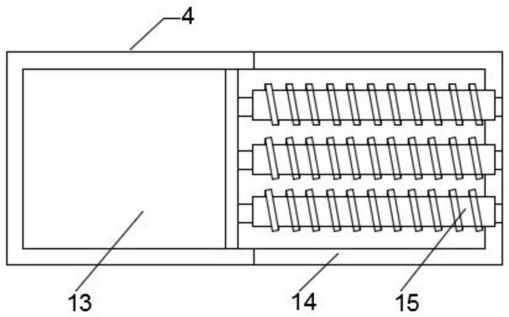
[0032] See Figure 1-5 As shown in a traction device applied to energy-channel traction vessel, inclusive guide rail 1, the rail 1 are attached to the pier 2 embedded, and to the top surface and both side surfaces of the guide rail 1 defines a chute 3 , the top of the card 1 is connected to a rod guide holder 4, a first fixing bracket 8 and the second fixing bracket 9, and the rod member is fixed on both sides of the bottom 4 of the guide rail 1 is provided with a first traction element 5, fixed to the lever member side of the card 4 is connected with a hydrauli...


PUM


Abstract

The invention discloses an energy-saving traction device applied to river ship traction. The device comprises a guide rail, embedded stone piers are installed at the two ends of the guide rail, sliding grooves are formed in the top face and the two side faces of the guide rail, a rod fixing piece, a first fixing support and a second fixing support are connected to the top of the guide rail in a clamped mode, first traction pieces are arranged on the two sides, close to the guide rail, of the bottom of the rod fixing piece, a hydraulic telescopic rod is clamped to one side of the rod fixing piece, a hydraulic cylinder is arranged on the outer side of the hydraulic telescopic rod, second traction pieces are arranged on the two sides, close to the guide rail, of the bottom of the first fixingsupport and the two sides, close to the guide rail, of the second fixing support, and a connecting piece is connected between the first fixing support and the second fixing support. The traction device of the invention can replace a traditional ship traction device, the structure is simple, the application range is wide, electric energy traction is adopted, environmental pollution is effectivelyreduced, energy conservation and environmental protection are achieved, excessive control does not need to be conducted manually, and social requirements are met.

Description

Technical field [0001] The present invention relates to the field of power devices, particularly relates to a traction device applied to energy-river ship towed. Background technique [0002] In running river vessels, in order to facilitate operation of the vessel, the vessel need to use traction means is pulled, it proceeds, traction power device arrangement is the vessel, providing power to the vessel so that the traveling speed of the vessel to maintain the stability in the river, thereby transporting goods to the designated location. [0003] Existing river vessels traction device has some disadvantages in use, substantially conventional energy-pulling means are pulled river vessels powered by diesel combustion, during use a large amount of exhaust gas, air pollution, and can consumption, high operating costs, do not have the energy saving effect and the need for manual manipulation of the whole traction device, each traction device is only applicable to a fixed tonnage of th...

Claims


Application Information

Patent Timeline
Patent Type & Authority Patents(China)
IPC IPC(8): B63B21/66
CPCB63B21/66
Inventor 童波
Owner 童波
Learn More