Supercharge Your Innovation With Domain-Expert AI Agents!

Chain plate leveling equipment for chain processing

A kind of chain plate and leveling technology, applied in conveyors, conveyor objects, transportation and packaging, etc., can solve the problems of low efficiency, time-consuming and laborious, and achieve the effect of convenient use, avoiding safety accidents and improving work efficiency.

Active Publication Date: 2021-04-06
绩溪山合机械有限公司
View PDF5 Cites 0 Cited by
  • Summary
  • Abstract
  • Description
  • Claims
  • Application Information

AI Technical Summary

Problems solved by technology

[0004] The purpose of the present invention is to solve the disadvantages of manual leveling of chain plates in the prior art, which is time-consuming, laborious and inefficient, and proposes a chain plate leveling equipment for chain processing

Method used


Image

  • Chain plate leveling equipment for chain processing
  • Chain plate leveling equipment for chain processing
  • Chain plate leveling equipment for chain processing

Examples


Embodiment 1

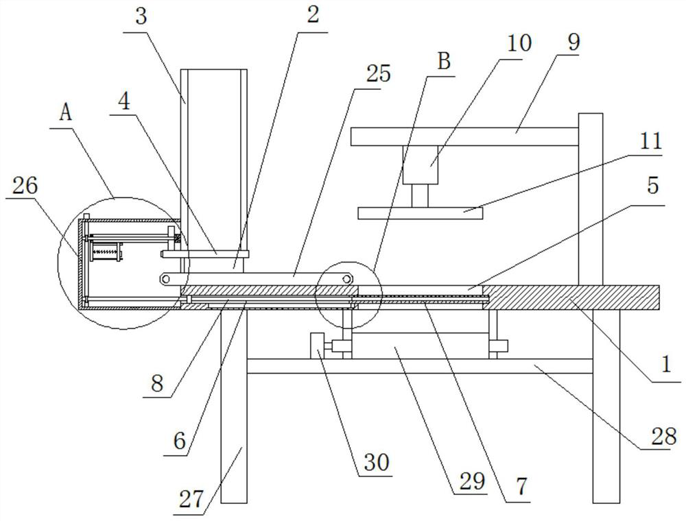
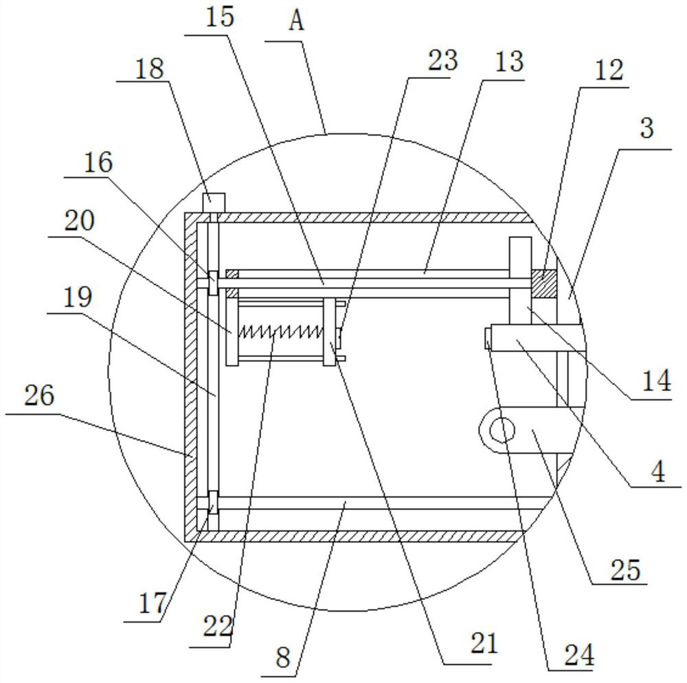
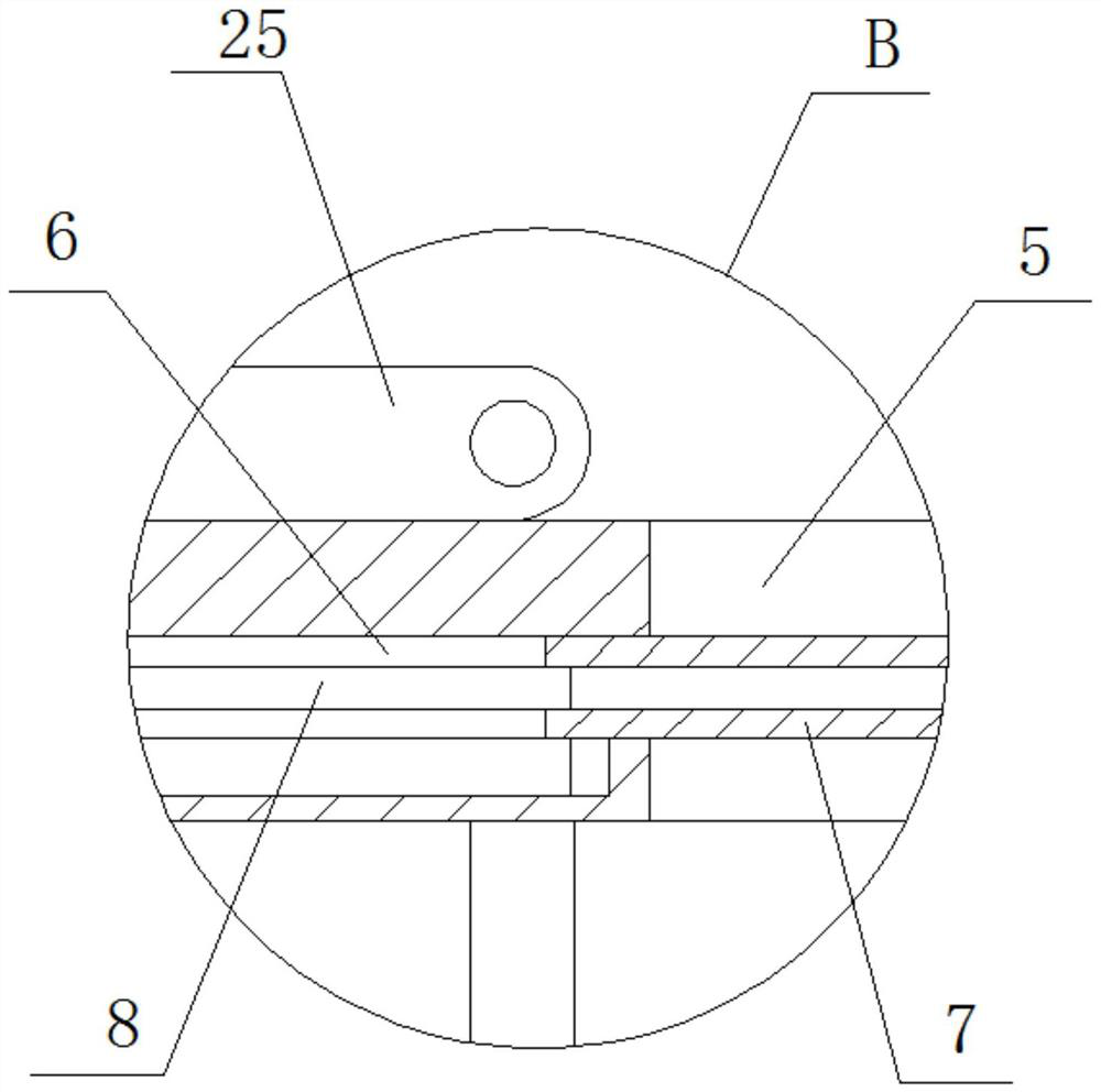
[0026] refer to Figure 1-5 , a chain plate leveling equipment for chain processing, comprising a processing table 1, a side plate 2 is fixedly installed on one side of the processing table 1, a material cylinder 3 located above the processing table 1 is fixedly installed on one side of the side plate 2, the material cylinder One side of the 3 is fixedly installed with a fixed plate 12, and the fixed plate 12 is provided with a rectangular vertical hole 13, and a connecting plate 14 is slidably installed in the rectangular vertical hole 13, and the bottom of the connecting plate 14 is fixedly installed with a baffle 4, and the baffle 4 The top is in contact with the bottom of the barrel 3, the top of the processing table 1 is provided with a first conveyor belt 25 below the baffle plate 4, the processing table 1 is provided with a discharge hole 5, and the inner wall of one side of the discharge hole 5 is provided with a Horizontal hole 6, a discharge plate 7 is slidingly inst...

Embodiment 2

[0035] refer to Figure 1-5, a chain plate leveling equipment for chain processing, comprising a processing table 1, one side of the processing table 1 is fixed with a side plate 2 by bolts, and one side of the side plate 2 is fixed with a material cylinder located above the processing table 1 by bolts 3. One side of the barrel 3 is fixed with a fixed plate 12 by bolts, and a rectangular vertical hole 13 is opened on the fixed plate 12, and a connecting plate 14 is slidably installed in the rectangular vertical hole 13, and the bottom of the connecting plate 14 is fixed by bolts. Baffle 4, the top of baffle 4 is in contact with the bottom of barrel 3, the top of processing table 1 is provided with the first conveyer belt 25 that is positioned at below baffle 4, and processing table 1 is provided with discharging hole 5, and discharging hole A horizontal hole 6 is provided on the inner wall of one side of the 5, and a discharge plate 7 is slidably installed in the horizontal ho...


PUM


Abstract

The present invention belongs to the field of chain processing, especially a chain plate leveling equipment for chain processing. Aiming at the problems that most of the existing chain plates are manually leveled, time-consuming and labor-intensive, and low in efficiency, the following scheme is proposed, which includes a processing table, One side of the processing table is fixedly installed with a side plate, one side of the side plate is fixedly installed with a material cylinder located above the processing table, one side of the material cylinder is fixedly installed with a fixing plate, and a rectangular vertical hole is opened on the fixing plate , a connection plate is slidably installed in the rectangular vertical hole, a baffle is fixedly installed on the bottom of the connection plate, the top of the baffle is in contact with the bottom of the barrel, and the top of the processing table is provided with a first conveyor belt below the baffle, The invention can conveniently level the chain plate, can automatically discharge and unload the material, does not require too much manual intervention, saves time and effort, improves work efficiency, avoids safety accidents caused by manual discharging, and has a simple structure and is convenient to use.

Description

technical field [0001] The invention relates to the technical field of chain processing, in particular to a chain plate smoothing device for chain processing. Background technique [0002] Chains are generally metal links or rings, which are mostly used for mechanical transmission and traction. Chains used to obstruct traffic passages (such as in streets, rivers or harbor entrances), chains for mechanical transmission, in similar products, according to the basic structure of the chain, that is, according to the shape of the element, the parts that mesh with the chain And position, size ratio between parts and other aspects to divide the chain product series to which it belongs. There are many types of chains, but their basic structures are only the following types, and the others are all deformations of these types. We can see from the above chain structures that most chains are composed of chain plates, chain pins, bushings and other components. The chain plates will be b...

Claims


Application Information

Patent Timeline
Patent Type & Authority Patents(China)
IPC IPC(8): B65G47/04B65G23/22B65G15/30B65G47/22B65G47/34
CPCB65G15/30B65G23/22B65G47/04B65G47/22B65G47/34B65G2201/022
Inventor 巫新锋
Owner 绩溪山合机械有限公司
Features
  • R&D
  • Intellectual Property
  • Life Sciences
  • Materials
  • Tech Scout
  • Unparalleled Data Quality
  • Higher Quality Content
  • 60% Fewer Hallucinations
Learn More