Shield station-crossing construction method capable of achieving layered backfill in small and narrow vertical shaft

A layered backfill and construction method technology, applied in the direction of filling, earth cube drilling, safety devices, etc., can solve the problems of time-consuming and labor-consuming, ground collapse, shaft flooding, etc., achieve high efficiency, reduce construction, avoid Effects of Structural Damage

Active Publication Date: 2020-04-10
CCFEB CIVIL ENG
View PDF6 Cites 0 Cited by
  • Summary
  • Abstract
  • Description
  • Claims
  • Application Information

AI Technical Summary

Problems solved by technology

The origination and reception are the first-level risk sources of shield tunneling construction. A slight inadvertence in the construction process will cause water and sand gushing, which will lead to risks such as the shaft being flooded and the ground collapsing.
The conventional subway shield adopts the method of setting up the guide platform and carrying out the empty push of the shield to carry out the receiving and starting transit. However, in the narrow shaft, due to the limited space, it is difficult to carry out construction, which is time-consuming and labor-intensive. Therefore, it is urgently needed A safe and fast shield tunneling method in a narrow space

Method used


Image

  • Shield station-crossing construction method capable of achieving layered backfill in small and narrow vertical shaft
  • Shield station-crossing construction method capable of achieving layered backfill in small and narrow vertical shaft
  • Shield station-crossing construction method capable of achieving layered backfill in small and narrow vertical shaft

Examples


Embodiment

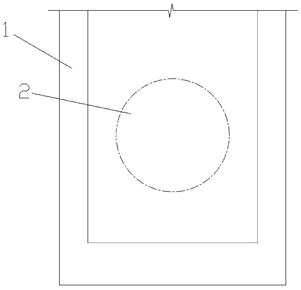
[0030] A shield tunneling construction method for layered backfilling in narrow shafts, please refer to Figure 1 to Figure 5 , which includes the following steps:

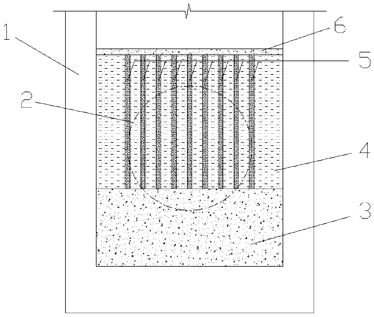
[0031] S1. Before the shield machine 10 passes through the station and after the bottom layer of the main structure of the shaft 1 is completed, backfill the hard backfill 3 in the shaft 1 to 0.5m~1.0m above the bottom of the portal 2; Backfill the undisturbed soil 4 after the backfill 3 is completed and reaches a certain strength. The undisturbed soil 4 is backfilled to 0.5m~1.0m above the top of the portal 2. In the process, small machines are used for layered compaction; among them, the hard backfill is made of pea stone, medium-coarse sand and cement in a mass ratio of 7:2:1;

[0032] S2. After the undisturbed soil 4 is backfilled and fully compacted, drill holes in the undisturbed soil 4 and inject ordinary Portland cement with a strength grade of 42.5 to form a cement pile 5. The diameter of the cement pile...


PUM


Abstract

The invention discloses a shield station-crossing construction method capable of achieving layered backfill in a small and narrow vertical shaft. The method of layered backfill is adopted to form soilwith certain strength, a shield tunneling machine can simulate a normal strata for tunneling during station crossing, on the first layer, a hard backfill material is backfilled, it is ensured that the backfill material has the enough bearing force, the too large sinking generated by self weight during station crossing of the shield tunneling machine is prevented, on the second layer, an originalsoil layer is backfilled, the phenomenon that during station-crossing propelling of the shield tunneling machine, too large resistance is generated, and a pipe segment is structurally damaged is avoided, a cement pile in the backfill soil increases the shield body torque resistance during tunneling of the shield tunneling machine, and the tunneling posture of the shield tunneling machine can be ensured. The method greatly reduces receiving and starting risks during shield station crossing, the hole door water burst sand burst ground collapse risk can be avoided, shield concrete guide platformconstruction, hole door water stop device mounting and an end reinforcing grouting material can be reduced, meanwhile, the time for mounting of a guide platform and other station-crossing materials inthe small and narrow vertical shaft can be omitted, and the shield construction proceed can be improved.

Description

technical field [0001] The invention belongs to the technical field of shield tunneling station passing construction, and specifically discloses a shield tunneling station passing construction method for layered backfilling in a narrow vertical shaft. Background technique [0002] With the acceleration of the urbanization process, more and more urban power tunnels are being built. Due to the optimization and innovation of technical processes, the construction of power tunnels using the shield method is becoming more and more common. At present, the urban high-voltage cable lines are long, and there are many intermediate cable exit wells. Therefore, in the process of shield tunneling construction, it is necessary to pass through the wells continuously. Most of them are narrow shaft structures. The origination and reception are the first-level risk sources of shield tunneling construction. A slight inadvertence in the construction process will cause water and sand gushing, wh...

Claims


Application Information

Patent Timeline
Patent Type & Authority Applications(China)
IPC IPC(8): E21D9/087E21F15/00
CPCE21D9/087E21F15/00E21F15/005
Inventor 陈亚军吕涛龙彪
Owner CCFEB CIVIL ENG
Why Eureka
Try Eureka