
Composite electromagnetic type dynamic vibration absorber

A dynamic vibration absorber and composite electromagnetic technology, which is applied in the field of vibration absorption, can solve the problems that the output force density and output force linearity cannot be taken into account.

Pending Publication Date: 2020-04-10
ZKZS ELECTRONICS TECH CO LTD
View PDF3 Cites 7 Cited by
  • Summary
  • Abstract
  • Description
  • Claims
  • Application Information

AI Technical Summary

Problems solved by technology

[0006] Therefore, the technical problem to be solved by the present invention is that the existing ampere force type vibration absorber or electromagnet type vibration absorber cannot balance the output force density and output force linearity

Method used


Image

  • Composite electromagnetic type dynamic vibration absorber
  • Composite electromagnetic type dynamic vibration absorber
  • Composite electromagnetic type dynamic vibration absorber

Examples


Embodiment 1

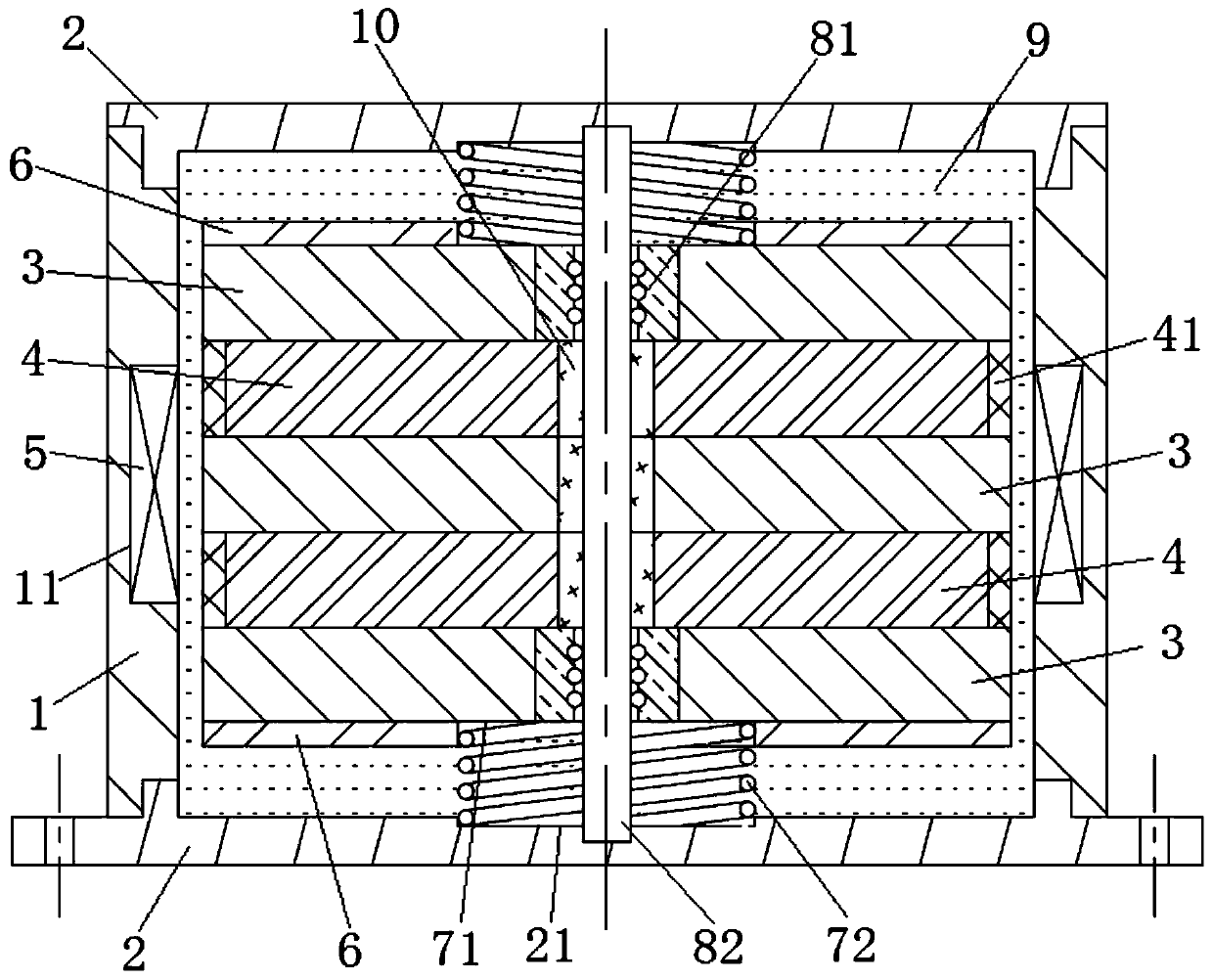
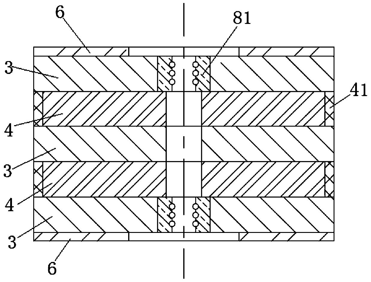
[0061] This embodiment provides a composite electromagnetic dynamic vibration absorber, which includes a housing 1 , two cover plates 2 , a mover, a vibration guide assembly, a coil 5 and a coil slot 11 . The two cover plates 2 are the upper cover plate and the lower cover plate respectively. The cover plate 2 is a flat plate structure, the outer shell 1 is closed in the circumferential direction, and has an open structure at both ends. The upper cover plate and the lower cover plate are respectively sealed in the shell 1 Both ends are open, forming a closed installation cavity with the shell 1, such as figure 1 As shown, stepped surfaces are provided at the openings at the upper and lower ends of the housing 1, and the corresponding two cover plates 2 are provided with matching stepped surfaces in the circumferential direction, and the two stepped surfaces are fitted together to form a seal. In this embodiment, the housing 1 Made of soft magnetic material. Mounting holes can...

Embodiment 2

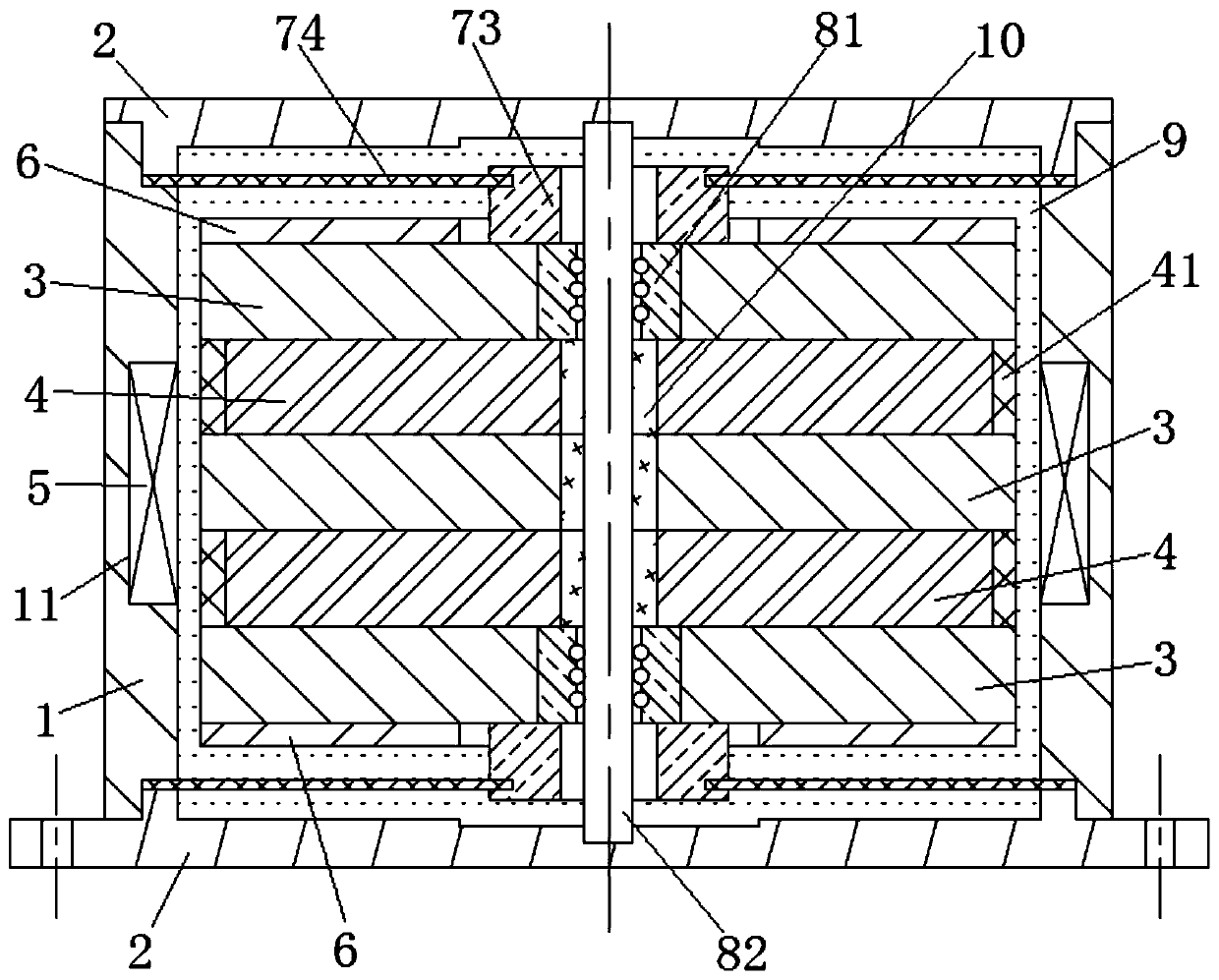
[0072] This embodiment provides a composite electromagnetic dynamic vibration absorber. Compared with the technical solution of Embodiment 1, the difference is that, as figure 2 As shown, the limit part in the vibration guide assembly adopts the flange 73, the flange 73 is coaxially threaded on the guide rod 82 and fixed on the mover core 3 at both ends of the mover, the flange 73 is located at the two ends of the auxiliary permanent In the inner ring of the magnet 6, the elastic member adopts a leaf spring 74, which is distributed symmetrically with respect to the flange 73. In this embodiment, the leaf spring 74 is circular, and the edge of the circular inner ring is fixed on the outer peripheral surface of the flange 73. , the edge of its outer ring is fixed on the inner step where the cover plate 2 and the casing 1 are sealed. When the mover is in a balanced state, the surface of the leaf spring 74 is arranged perpendicular to the axial direction of the mover.

[0073] As...


PUM


Abstract

The invention provides a composite electromagnetic type dynamic vibration absorber. According to the composite electromagnetic type dynamic vibration absorber, a shell is made of a soft magnetic material, a coil groove is formed in the inner wall surface of the shell, when a rotor is at a balanced position, in the axial direction of the rotor, the upper groove opening edge of the coil groove is located between the N-pole surface and the S-pole surface of an upper main permanent magnet, the lower groove opening edge of the coil groove is located between the N-pole surface and the S-pole surfaceof a lower main permanent magnet, a coil is installed in the coil groove, when forward current flows through the coil, the rotor is subjected to downward electromagnetic force, meanwhile, the partialwire in the middle of the coil is affected by a magnetic field facing inwards in the radial direction, the coil can bear upward ampere force according to the left-hand rule, the rotor can bear downward counter-acting force according to the Newton's third law, namely when the forward current flows through the coil, the rotor can bear downward electromagnetic force and ampere force at the same time, when reverse current flows through the coil, the rotor can bear upward electromagnetic force and ampere force at the same time, and vibration is counteracted through the combined action of the electromagnetic force and the ampere force.

Description

technical field [0001] The invention belongs to the technical field of vibration absorption, and in particular relates to a composite electromagnetic dynamic vibration absorber. Background technique [0002] In many industrial fields, mechanical vibration is an engineering problem that cannot be ignored. Vibration absorbers are widely used as a common means of vibration control, and active vibration absorption, as the ultimate form of vibration absorbers, can suppress vibration to the greatest extent. [0003] The main methods of traditional active electromagnetic vibration absorber to generate electromagnetic force are: (1) Ampere force type vibration absorber: Most of this type of vibration absorber is surrounded by circumferential wires, and the current-carrying wires generate Ampere force under the action of radial magnetic field. This type of vibration absorber needs to place the coil in the air gap, and the coil is energized to generate an ampere force in the air gap ...

Claims


Application Information

Patent Timeline
IPC IPC(8): F16F7/10F16F7/104F16F7/116
CPCF16F7/1011F16F7/104F16F7/116F16F2230/0029F16F2238/022F16F2238/026
Inventor 张维李东昱闫政涛陈凡杨预立
Owner ZKZS ELECTRONICS TECH CO LTD
Learn More