A vapor chamber and its internal structure manufacturing method

A technology of internal structure and manufacturing method, applied in indirect heat exchangers, lighting and heating equipment, modification through conduction and heat transfer, etc., can solve problems such as high manufacturing cost, complicated process, and environmental pollution

Active Publication Date: 2021-06-15
DONGGUAN LINGJIE PRECISION MACHINING TECH CO LTD
View PDF4 Cites 0 Cited by
  • Summary
  • Abstract
  • Description
  • Claims
  • Application Information

AI Technical Summary

Problems solved by technology

[0003] The upper and lower covers of the traditional vapor chamber are manufactured by wet etching. This method uses a large amount of oxidants and strong acids, and the waste water produced causes great pollution to the environment. At the same time, this process also uses photolithography, masks, etc. Process, complex process, high manufacturing cost

Method used


Image

  • A vapor chamber and its internal structure manufacturing method
  • A vapor chamber and its internal structure manufacturing method
  • A vapor chamber and its internal structure manufacturing method

Examples


Embodiment 1

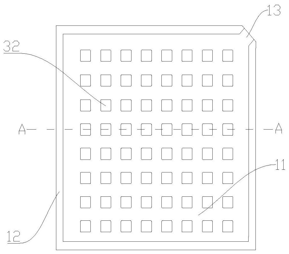
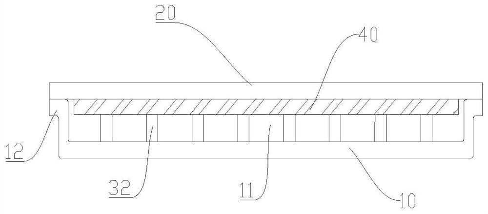
[0039] figure 1 and figure 2 A vapor chamber according to the invention is schematically shown. As shown, the device includes a first cover 10 and a second cover 20 . Wherein, a groove 11 is processed in the middle of the first cover plate 10 , and a plurality of support columns 32 are evenly distributed in the groove 11 . The support column 32 is a square column with uniform up and down. The edge of the first cover plate 10 is processed into a welded edge 12, and the welded edge 12 and the edge of the second cover plate 20 are attached to each other and sealed. The second cover plate 20 is sealingly connected with the first cover plate 10 , so that the groove 11 becomes a cavity, and the support column 32 is located in the cavity. A liquid-absorbing core 40 is also provided inside the cavity, and one side of the liquid-absorbing core 40 is connected with the inner side of the second cover plate 20, and the other side is connected with the support column 32. The vapor ch...

Embodiment 2

[0061] Figure 4 and Figure 5 Another vapor chamber according to the present invention is schematically shown. The difference from Embodiment 1 is that the first cover plate 10 , the second cover plate 20 and the support column 32 are all made of aluminum. The support column 32 is cylindrical, and the support column 32 is in point contact with the liquid-absorbent wick 40 .

[0062] The vapor chamber of this embodiment differs from that of Embodiment 1 in the processing method in that:

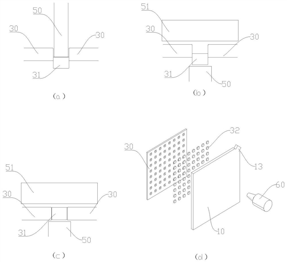
[0063] In step (2), the aluminum material is used to process the supporting column 32 . The processing of the supporting column 32 adopts the method of punching and direct blanking, and a plurality of cylindrical supporting columns 32 are stamped from the plate 30 in one step. Such as Figure 6 As shown, the support column 32 can be placed in the jig 70 . The jig 70 is provided with a plurality of evenly distributed holes for the positioning of the support column 32 , which function as a ...


PUM


Abstract

The invention discloses a manufacturing method of a soaking plate and its internal structure, comprising the following steps: processing grooves and welding edges on the first cover plate and reserving a material injection port by using a stamping process, and processing the second cover plate into a flat plate ; weld a plurality of support columns in the groove of the first cover; attach a liquid-absorbing core on the inner wall of the first cover or the inner wall of the second cover; attach the first cover and the second cover to each other Combined to form a cavity, the support column and the liquid-absorbing core are located in the cavity; the edge of the first cover and the second cover are welded; the cavity communicates with the outside through the injection port; the cavity is filled with workers through the injection port After massaging, the air inside the cavity is extracted through the injection port, and then the injection port is blocked and sealed to form a vapor chamber. The method of the invention adopts a stamping process to process the soaking plate and its internal support structure, the method is simple and easy to operate, and the production efficiency is improved; in addition, the use of a large amount of chemical reagents is avoided, and the method is safe and pollution-free.

Description

technical field [0001] The invention relates to the technical field of vapor chamber manufacturing, in particular to a method for manufacturing a vapor chamber and its internal structure. Background technique [0002] With the rapid development of 5G wireless communications, radar, drones, satellites and other fields, the application prospects of high-power radio frequency chips are becoming more and more broad. The operating speed of the chip will be greatly improved, and the heat generated by it will also increase accordingly. Ensuring its stable operation has become the top priority. Therefore, the demand and challenges for the vapor chamber will also follow, and its industrial layout will be accelerated. There is no delay. [0003] The upper and lower covers of the traditional vapor chamber are manufactured by wet etching. This method uses a large amount of oxidants and strong acids, and the waste water generated causes great pollution to the environment. At the same ti...

Claims


Application Information

Patent Timeline
Patent Type & Authority Patents(China)
IPC IPC(8): F28D15/04H05K7/20
CPCF28D15/0283F28D15/043H05K7/20509
Inventor 李海禄梁平平陈驰
Owner DONGGUAN LINGJIE PRECISION MACHINING TECH CO LTD
Why Eureka
Try Eureka