Angle self-correction method and system based on multi-frequency excitation

A multi-frequency, self-correcting technology, applied in the use of electromagnetic means, measuring devices, instruments, etc., can solve the problems of high installation requirements, increased application costs, installation errors, etc., and achieves easy operation, simple process, and practicality. high effect

Active Publication Date: 2020-04-10
深圳市智能机器人研究院
View PDF15 Cites 0 Cited by
  • Summary
  • Abstract
  • Description
  • Claims
  • Application Information

AI Technical Summary

Problems solved by technology

The Chinese patent (application number 201710720507.8) describes a method for optimizing the layout of the reading head for self-calibration. This patent is used to improve the installation of the reading head in the EDA method and expand the application of the EDA method, but it still needs to install multiple Readhead, no hardware cost reduction
However, this method obviously has the following shortcomings: 1. The installation accuracy of multiple reading heads is limited by the structural size of the encoder; 2. For encoders with too small diameter, when the number of reading heads is greater than 3, there will be serious installation errors; 3. It is impossible to install the reading head in infinite equal parts on a circle, and the position of each reading head needs to ensure a high degree of consistency, so that the effect of the EDA method is obvious
The performance is as follows: (1) The EDA method needs to install multiple reading heads, which has high installation requirements and increases the application cost; (2) the traditional correction method needs to collect a large amount of position data at equal intervals throughout the week, and the process is cumbersome and responsible, time-consuming and laborious ; (3) Existing methods all need to rely on external instruments, or construct multiple reading heads by physical methods

Method used


Image

  • Angle self-correction method and system based on multi-frequency excitation
  • Angle self-correction method and system based on multi-frequency excitation
  • Angle self-correction method and system based on multi-frequency excitation

Examples


Embodiment Construction

[0044] The present invention will be further explained and described below in conjunction with the accompanying drawings and specific embodiments of the description. For the step numbers in the embodiment of the present invention, it is only set for the convenience of explanation and description, and there is no limitation on the order of the steps. The execution order of each step in the embodiment can be carried out according to the understanding of those skilled in the art Adaptive adjustment.

[0045] Aiming at the defects existing in the existing correction system, the present invention focuses on solving many disadvantages of the traditional method when the magnetic encoder is corrected. The invention makes a better attempt on the effectiveness, practicability and other aspects of the self-correcting system of the magnetic encoder.

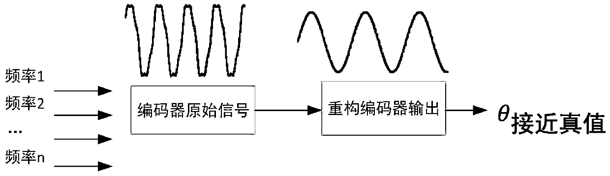
[0046] The present invention mainly relies on multiple frequency excitation signals to excite a single reading head instead of the tradition...


PUM


Abstract

The invention discloses an angle self-correction method and system based on multi-frequency excitation, and the system comprises a multi-frequency signal generation module which is used for generatingan excitation signal containing a plurality of frequencies, injecting the excitation signal into a coil, and generating a magnetic field; the high-speed ADC module which is used for carrying out equal time difference sampling on output signals generated by electromagnetic induction and converting the sampled output signal into a digital signal; the microprocessor module which is used for controlling the sampling time sequence of the high-speed ADC module and extracting the phase of the digital signal by using a Fourier transform method to obtain an angle function of the measured rotating object at each frequency; and the self-correction module which is used for carrying out self-extraction of error parameters on the angle function and correcting the angular displacement sensor according to the error parameters. The method is low in cost and high in practicability, and can be widely applied to the technical field of displacement measurement.

Description

technical field [0001] The invention relates to the technical field of displacement measurement, in particular to an angle self-correction method and system based on multi-frequency excitation. Background technique [0002] Electromagnetic encoder usually includes two parts: magnetic pole and reading head. The reading head injects a single high-frequency excitation signal, then modulates the angular displacement to realize angular displacement measurement, and then cooperates with the space equalization technology to reasonably and evenly distribute the magnetic poles to achieve better The purpose of high-precision displacement measurement. According to the way the magnetic field is generated, magnetic encoders can be divided into electromagnetic encoders and permanent magnet encoders that rely on alternating current excitation coils for electromagnetic induction. When the electromagnetic encoder modulates the signal, it contains the repeated conversion process of "electric...

Claims


Application Information

Patent Timeline
Patent Type & Authority Applications(China)
IPC IPC(8): G01B7/30G01B7/02
CPCG01B7/02G01B7/30
Inventor 王伟毕盛陈江城陈丽燕
Owner 深圳市智能机器人研究院
Why Eureka
Try Eureka