Laser virtual interaction system and method based on liquid crystal photoelectric effect

A photoelectric effect and virtual interaction technology, applied in the fields of microelectronics and optics, can solve the problems of unsatisfactory scanning speed and durability, unfavorable integration, large product volume, etc., and achieve easy production process, short response time and sensitive system Effect

Pending Publication Date: 2020-04-10
SOUTH UNIVERSITY OF SCIENCE AND TECHNOLOGY OF CHINA
View PDF9 Cites 0 Cited by
  • Summary
  • Abstract
  • Description
  • Claims
  • Application Information

AI Technical Summary

Problems solved by technology

However, due to factors such as dynamic inertia and loss of components, the scanning speed and durability of this mechanical scanning chip are not satisfactory
Due to the limitation of its scanning speed, in this kind of mechanical scanning interactive system, the delay of operation is relatively common
Moreover, the assembled product of this mechanical system is relatively large, which hinders its integration into smaller size applications

Method used


Image

  • Laser virtual interaction system and method based on liquid crystal photoelectric effect
  • Laser virtual interaction system and method based on liquid crystal photoelectric effect
  • Laser virtual interaction system and method based on liquid crystal photoelectric effect

Examples


Embodiment 1

[0037] Example 1:

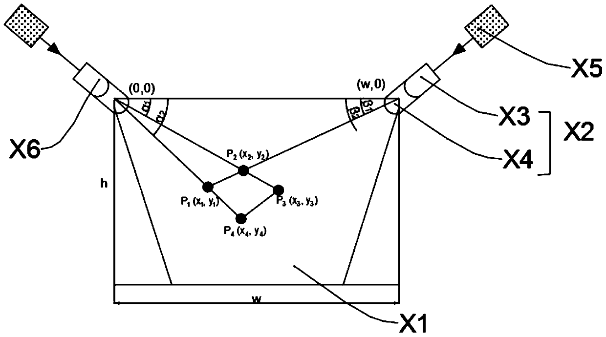
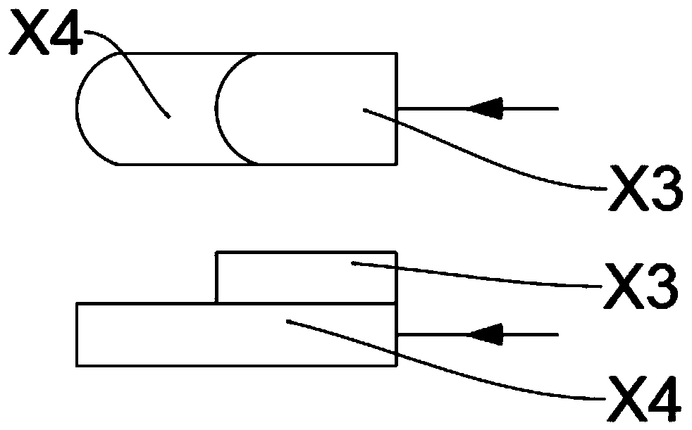
[0038] Such as figure 1 , figure 2 , a laser virtual interactive system based on liquid crystal photoelectric effect, including a working plane X1, a first laser scanning positioning system X2 and a second laser scanning positioning system X6 are set on the working plane, and the laser scanning positioning system includes a light emitter X5 and an infrared photoelectric probe X3 and the light transmitter X5 are connected with a laser scanning chip X4, and the laser scanning chip X4 regulates the laser to deflect and realize light scanning.

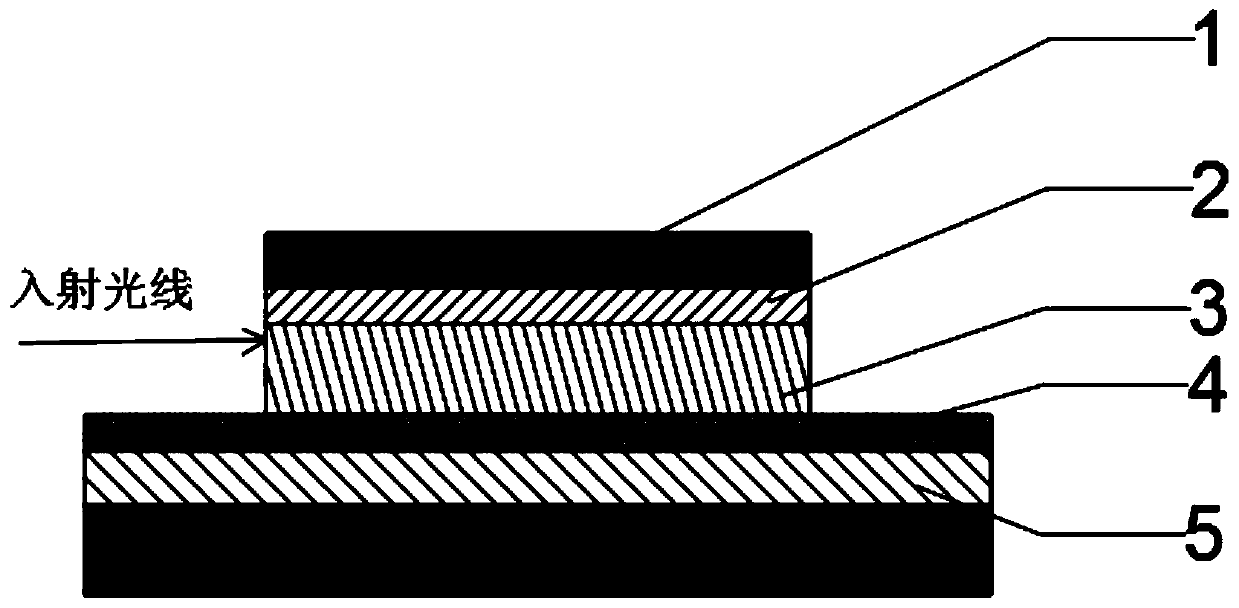
[0039] Such as image 3 , preferably, the laser scanning chip X4 includes a liquid crystal layer 3, an electrode driving layer 1 is arranged above the liquid crystal layer, an electrode driving device 2 is arranged above the electrode driving layer 1, and a photoconductive layer is provided below the liquid crystal layer 3, and the photoconductive layer includes a first The layer structure 4 and the second layer str...

Embodiment 2

[0052] In practical applications, the angle of the optical chip for liquid crystal scanning has certain limitations. In order to achieve a wider range of scanning angles, we can superimpose two or more chips with smaller scanning angles. Therefore, embodiment 2 is provided, as Figure 6 shown. Similarly, in this embodiment, the maximum scanning angle of a single optical chip used is about 50°, the width w of the working plane is 5m, and the height h is 3m. In other embodiments, other data can be used to realize the same technology Effect.

[0053] In Embodiment 2, the laser scanning system in Embodiment 1 is set to include a first light emitter and a second light emitter, the first light emitter is connected to the first laser scanning chip X41, and the second light emitter is connected to the second laser The scanning chip X42, the first laser scanning chip X41 and the second laser scanning chip X42 are arranged side by side so that the light deflection boundary of the first...

Embodiment 3

[0059] In this embodiment, a laser virtual interaction method based on liquid crystal photoelectric effect is also provided, including the following steps:

[0060] (1) Control the laser scanning chip in each group of laser scanning positioning system, adjust the light transmitter to deflect the light at a certain frequency, so as to realize scanning;

[0061] (2) Utilize the infrared photoelectric probes in each group of laser scanning positioning systems to determine the position of the scanning target in each group of laser scanning positioning systems through the time difference between the photoelectric probe receiving time and the light emitting time;

[0062] (3) Utilize the positions of different groups of laser scanning positioning systems and the positions in each group of laser scanning positioning systems to determine the final position of the scanning target;

[0063] (4) By adjusting the frequency of the laser scanning chip, real-time scanning of the motion track...


PUM


Abstract

The invention discloses a laser virtual interaction system based on a liquid crystal photoelectric effect. The system comprises a working plane, at least two groups of laser scanning and positioning systems are arranged on the working plane, each laser scanning and positioning system comprises a light emitter and an infrared photoelectric probe, the light emitter is connected with a laser scanningchip, and the laser scanning chip regulates and controls laser to deflect to realize light scanning. The laser scanning speed and frequency controlled by the liquid crystal voltage are higher and canreach 5 kHz or above. In the system, main components responsible for laser deflection do not comprise movable mechanical structures, so that the system is not influenced by physical inertia. On the contrary, deflection of the liquid crystal is controlled by a voltage signal, and the limit response speed of the liquid crystal is more sensitively affected by a liquid crystal material and the scanning chip. Therefore, the interactive system for liquid crystal scanning and positioning is shorter in response time and more sensitive.

Description

technical field [0001] The invention relates to the fields of microelectronics and optics, in particular to a laser virtual interaction system and an interaction method based on liquid crystal photoelectric effect. Background technique [0002] The interactive system based on infrared scanning has huge market application potential, through the coverage of one or more infrared scanning, any plane, such as a wall or office desktop, can be made to have an operable touch screen function. Now, the market in this area is growing rapidly, such as virtual keyboards, touch screen interactive projectors and so on. The most critical component in realizing this function is the laser scanning optical chip, and most of the current scanning components realize laser scanning by mechanically changing the angle of the mirror surface. However, due to factors such as dynamic inertia and loss of components, the scanning speed and durability of this mechanical scanning chip are not satisfactory....

Claims


Application Information

Patent Timeline
Patent Type & Authority Applications(China)
IPC IPC(8): G06F3/041G06F3/042G02F1/133G02F1/1343G02B26/10
CPCG06F3/0412G06F3/0425G02F1/13306G02F1/134309G02B26/10
Inventor 娄飞邱成峰刘红均
Owner SOUTH UNIVERSITY OF SCIENCE AND TECHNOLOGY OF CHINA
Why Eureka
Try Eureka