
Design method of novel ultrasonic grinding vibration system

A technology of vibration system and design method, applied in the direction of geometric CAD, etc., can solve the problems of design results and actual deviation, ignore the influence of longitudinal vibration ultrasonic horn bending vibration, affect the performance of ultrasonic grinding vibration system, etc.

Pending Publication Date: 2020-04-10
DALIAN JIAOTONG UNIVERSITY
View PDF0 Cites 3 Cited by
  • Summary
  • Abstract
  • Description
  • Claims
  • Application Information

AI Technical Summary

Problems solved by technology

[0004] At present, in the design of ultrasonic grinding vibration system, the disc connected with the longitudinal vibration ultrasonic horn is designed as a general disc. This kind of design method has the following shortcomings: (1) The longitudinal vibration ultrasonic horn is ignored. The impact on the bending vibration of the disk; (2) the second kind of Bessel function in the vibration displacement function of the non-center area of ​​the disk is omitted (the second kind of Bessel function approaches to Infinity), so it is only suitable for ultrasonic grinding vibration system with small disc diameter
This type of design method has large design errors, which will affect the performance of the ultrasonic grinding vibration system and increase the time and cost of later debugging, especially the connection area between the longitudinal vibration ultrasonic horn and the disc is large or the diameter of the disc is large Sometimes, there may even be a serious deviation between the design result and the actual situation, resulting in design failure

Method used


Image

  • Design method of novel ultrasonic grinding vibration system
  • Design method of novel ultrasonic grinding vibration system
  • Design method of novel ultrasonic grinding vibration system

Examples


Embodiment Construction

[0083] In order to make the purpose, technical solutions and advantages of the embodiments of the present invention clearer, the technical solutions in the embodiments of the present invention will be clearly and completely described below in conjunction with the drawings in the embodiments of the present invention. Obviously, the described embodiments It is a part of embodiments of the present invention, but not all embodiments. Based on the embodiments of the present invention, all other embodiments obtained by persons of ordinary skill in the art without making creative efforts belong to the protection scope of the present invention.

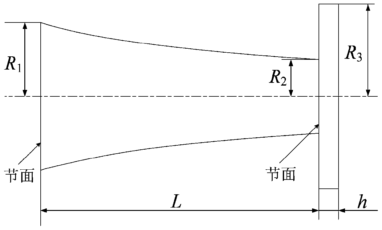
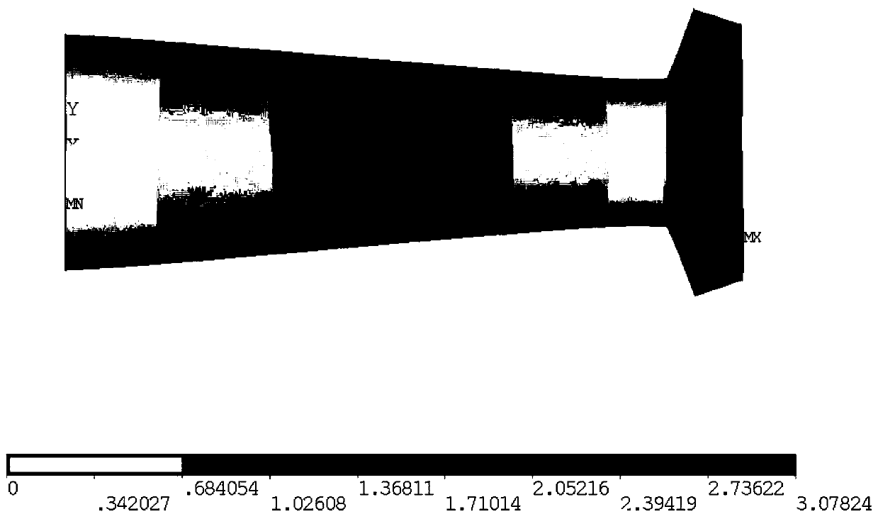
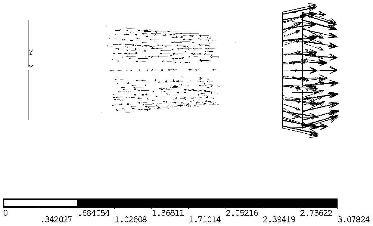
[0084] Such as Figure 1~4 As shown, a novel ultrasonic grinding vibration system design method, the novel ultrasonic grinding vibration system includes an ultrasonic horn and a grinding wheel disk fixedly connected to the small end of the ultrasonic horn, the ultrasonic horn The length of the rod is L, and the outer diameter of the large en...


PUM


Abstract

The invention discloses a design method of a novel ultrasonic grinding vibration system. The novel ultrasonic grinding vibration system comprises an ultrasonic amplitude-change pole and a grinding wheel disc fixedly connected with a small end of the ultrasonic amplitude-change pole, the length of the ultrasonic amplitude-change pole is L, the outer diameter of a large end of the ultrasonic amplitude-change pole is R1, the outer diameter of a small end of the ultrasonic amplitude-change pole is R2, and the outer diameter of the grinding wheel disc is R3. The method comprises the following steps: S1, determining the length L of the ultrasonic amplitude-change pole, calculating an L value according to a formula sinkL=0, wherein the L value is wavelength is one half or integral multiple of that of the ultrasonic wave; S2, establishing a disc bending vibration frequency equation and determining R3 of the grinding wheel disc. According to the method, the problem that an existing design method is large in design error is solved, the high-precision design of the ultrasonic grinding vibration system is achieved, and the later debugging time and cost are reduced.

Description

technical field [0001] The invention relates to a design method of an ultrasonic grinding system, in particular to a novel ultrasonic grinding vibration system. Background technique [0002] Ultrasonic grinding technology is a processing technology that applies ultrasonic vibration to the grinding tool or workpiece, and uses the joint action of ultrasonic vibration and grinding tool to achieve higher processing quality and processing efficiency. One of the important technologies for high-quality and efficient processing of brittle materials and new composite materials. Ultrasonic grinding vibration system is the core equipment for ultrasonic grinding. The design of ultrasonic grinding vibration system determines the effect of ultrasonic in ultrasonic grinding, thus affecting the processing performance of ultrasonic grinding. The accuracy of the design method of the ultrasonic grinding vibration system determines the performance of the ultrasonic grinding vibration system an...

Claims


Application Information

Patent Timeline
IPC IPC(8): G06F30/17B24B1/04
CPCB24B1/04Y02T90/00
Inventor 马付建李君豪刘宇杨大鹏张生芳沙智华
Owner DALIAN JIAOTONG UNIVERSITY
Learn More