Subway contact network abrasion measuring method and system based on 3D structured light camera
A measurement method and structured light technology, applied in the direction of measuring devices, optical testing flaws/defects, using optical devices, etc., can solve the problems of discontinuous measured values, high intensity, and low measurement efficiency
- Summary
- Abstract
- Description
- Claims
- Application Information
AI Technical Summary
Problems solved by technology
Method used
Image
Examples
Embodiment 1
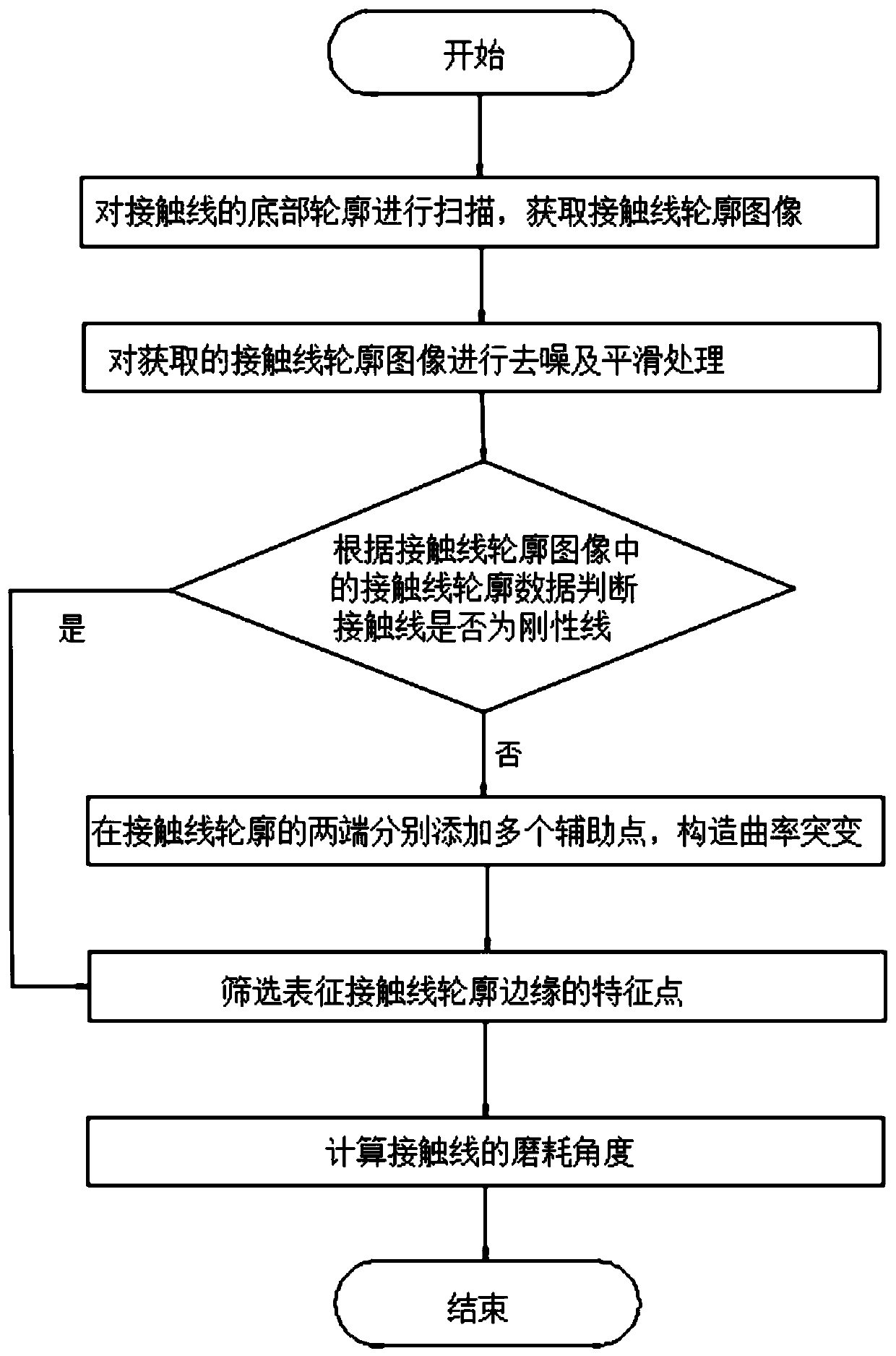
[0091] refer to figure 1 , a method for measuring the wear of a subway catenary based on a 3D structured light camera, comprising the following steps,
[0092] S1: Scan the bottom contour of the contact line, acquire the contour image of the contact line, and execute S2.
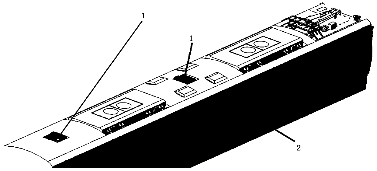
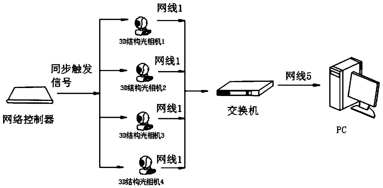
[0093] refer to figure 2 , 3 , in this embodiment, four 3D structured light cameras 1 are installed on the roof of the subway 2 at a certain distance to scan the bottom contour of the contact line. Before scanning, the 3D structured light camera 1 is first calibrated, and a horizontal calibration plane with weak reflection is placed on the laser of the 3D structured light camera 1 for calibration, and then the region of interest, exposure, and point distance are set and calibrated. Send a synchronous trigger signal to the four 3D structured light cameras, so that the four 3D structured light cameras work synchronously. Secondly, through the subway movement, the horizontal coordinates of the four 3D struc...
Embodiment 2
[0135] refer to figure 1 , a method for measuring the wear of a subway catenary based on a 3D structured light camera, comprising the following steps,
[0136] S1: Scan the bottom contour of the contact line, acquire the contour image of the contact line, and execute S2.
[0137] refer to figure 2 , 3 , in this embodiment, four 3D structured light cameras 1 are installed on the roof of the subway 2 at a certain distance to scan the bottom contour of the contact line. Before scanning, the 3D structured light camera 1 is first calibrated, and a horizontal calibration plane with weak reflection is placed on the laser of the 3D structured light camera 1 for calibration, and then the region of interest, exposure, and point distance are set and calibrated. Secondly, through the movement of the subway 2, the horizontal coordinates of the four 3D structured light cameras 1 are translated, and the forced splicing in the X-axis direction is realized, so as to complete the scanning o...
Embodiment 3
[0181] refer to figure 2 , 3 , a metro catenary wear measurement system based on a 3D structured light camera, including
[0182] The image acquisition unit includes a plurality of 3D structured light cameras 1, and the plurality of 3D structured light cameras 1 are located on the same horizontal calibration plane and arranged along the length direction of the contact line, and are used to scan the bottom of the contact line and obtain a profile image of the contact line .
[0183] refer to figure 2 , 3 , in this embodiment, four 3D structured light cameras 1 are installed on the roof of the subway 2 at a certain distance to scan the bottom contour of the contact line. Before scanning, the 3D structured light camera 1 is first calibrated, and a horizontal calibration plane with weak reflection is placed on the laser of the 3D structured light camera 1 for calibration, and then the region of interest, exposure, and point distance are set and calibrated. Send a synchronou...
PUM
 Abstract
Description
Claims
Application Information
 - R&D
- Intellectual Property
- Life Sciences
- Materials
- Tech Scout
- Unparalleled Data Quality
- Higher Quality Content
- 60% Fewer Hallucinations
Browse by: Latest US Patents, China's latest patents, Technical Efficacy Thesaurus, Application Domain, Technology Topic, Popular Technical Reports.
© 2025 PatSnap. All rights reserved.Legal|Privacy policy|Modern Slavery Act Transparency Statement|Sitemap|About US| Contact US: help@patsnap.com


