Laser fiber coupler with low-mode dispersion

A fiber optic coupler and low-mode technology, applied in the field of couplers, can solve problems such as increasing temperature difference and accelerating heat diffusion, and achieve the effect of increasing temperature difference, accelerating heat diffusion, and increasing diffusion area

Active Publication Date: 2020-04-10
福州市纳飞光电科技有限公司
View PDF5 Cites 0 Cited by
  • Summary
  • Abstract
  • Description
  • Claims
  • Application Information

AI Technical Summary

Problems solved by technology

[0006] Aiming at the problems existing in the prior art, the object of the present invention is to provide a laser fiber coupler with low mode dispersion, which can set side thermal diffusion on the diaphragm between the gain medium and the focusing mirror in the coupler. On the one hand, it can effectively isolate the heat generated by the pump light on the surface of the diaphragm. On the one hand, it can effectively control the heat diffusion direction of the side thermal diffusion plate to the outside away from the focusing mirror. On the other hand, it can dissipate the heat from the pump The location where the Pu light is irradiated spreads outwards in the longitudinal direction, which effectively increases the heat diffusion area and makes the heat more evenly distributed, thus effectively preventing the heat from spreading to the side of the focusing mirror at the position where the local temperature is too high. And the design of the outer diffusion ring can effectively increase the temperature difference, thereby reducing the accelerated heat diffusion in the longitudinal direction of the diaphragm surface, thereby effectively reducing the offset during light coupling, and effectively improving the use effect of the coupler

Method used


Image

  • Laser fiber coupler with low-mode dispersion
  • Laser fiber coupler with low-mode dispersion
  • Laser fiber coupler with low-mode dispersion

Examples


Embodiment 1

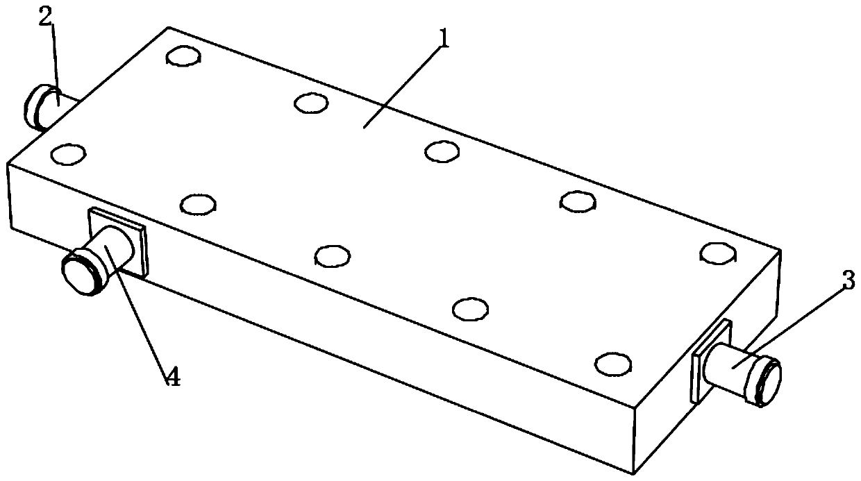
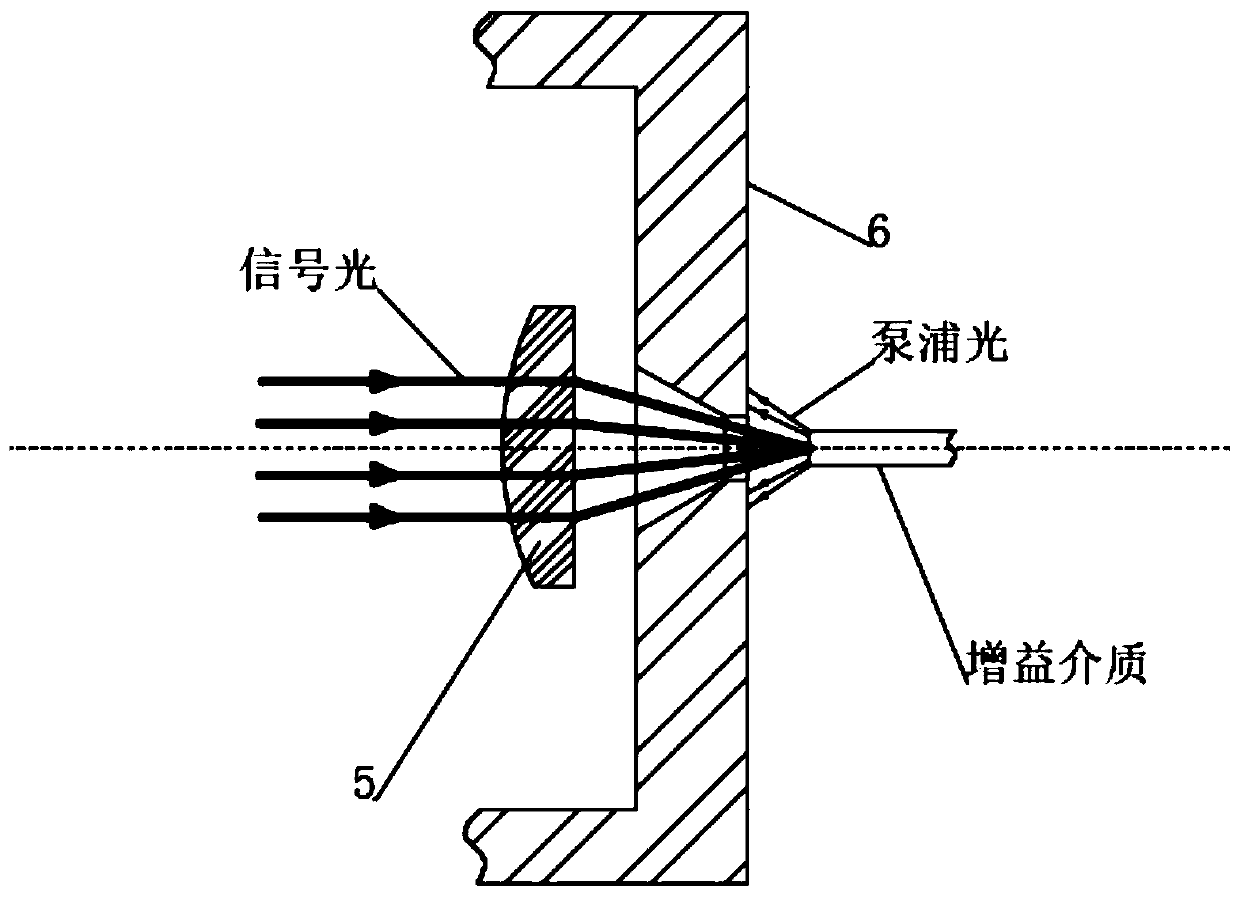
[0041] see Figure 1-2 , a low mode dispersion laser fiber coupler, comprising a coupler body 1, the left and right ends of the coupler body 1 are respectively connected to an input port 2 and an output port 3, the front end of the coupler body 1 is connected to a coupling port 4, the coupler body 1. A focusing mirror 5 is installed inside, and the outer cover of the focusing mirror 5 is provided with a diaphragm 6.

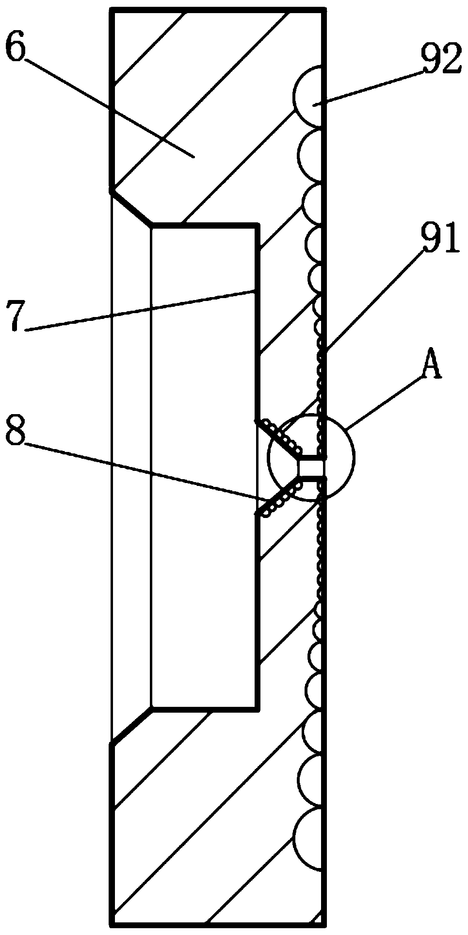
[0042] see image 3 , the end of the diaphragm 6 close to the focusing mirror 5 is dug with a cavity 7, the cavity 7 matches the focusing mirror 5, the inner wall of the cavity 7 and the focusing mirror 5 is dug with a diaphragm hole 8, and the coupler body 1 is also connected There is a gain medium, the gain medium is located on the right side of the diaphragm 6, the focusing mirror 5, the cavity 7, the diaphragm hole 8 and the gain medium are arranged in sequence from left to right, and the four are located on the same center line, and the diaphragm 6 is close...


PUM


Abstract

The invention discloses a laser optical fiber coupler with low-mode dispersion, belongs to the field of couplers, according to the laser optical fiber coupler with low-mode dispersion, a side edge heat diffusion plate can be arranged on a diaphragm between a gain medium in a coupler and a focusing mirror, on one hand, heat generated by the pump light can be effectively isolated on the surface of the diaphragm, the diffusion direction of heat of the side edge heat diffusion plate is effectively controlled to be diffused towards the outer side away from the focusing lens; on the other hand, heatcan be diffused outwards in the longitudinal direction from the irradiation position of the pump light; the heat diffusion area is effectively increased; the heat is uniformly distributed; the condition that the heat at the position with over-high local temperature spreads to one side of the focusing lens is effectively avoided; meanwhile, through the design of the inner heat gathering ring and the outer diffusion ring, the temperature difference can be effectively increased, longitudinal diffusion of accelerated heat on the surface of the diaphragm is reduced, the offset during light coupling is effectively reduced, and the using effect of the coupler is effectively improved.

Description

technical field [0001] The invention relates to the field of couplers, in particular to a laser fiber coupler with low mode dispersion. Background technique [0002] In a microwave system, it is often necessary to divide the microwave power of one path into several paths in proportion, which is the problem of power allocation. The components that realize this function are called power distribution components or couplers, which mainly include: directional couplers, power dividers and various microwave branch devices. [0003] A photocoupler is an electrical-optical-electrical conversion device that transmits electrical signals through light as a medium. It consists of two parts: the light source and the light receiver. The light-emitting source and the light-receiving device are assembled in the same airtight casing, and they are separated by transparent insulators. The pin of the light source is the input end, and the pin of the light receiver is the output end. The commo...

Claims


Application Information

Patent Timeline
Patent Type & Authority Applications(China)
IPC IPC(8): H01S3/042H01S3/04
CPCH01S3/0401H01S3/0405H01S3/042
Inventor 曹宇
Owner 福州市纳飞光电科技有限公司
Why Eureka
Try Eureka