Eureka AIR delivers breakthrough ideas for toughest innovation challenges, trusted by R&D personnel around the world.

Anti-static interference power distribution cabinet

An anti-static, power distribution cabinet technology, applied in the direction of static electricity, substation/distribution device shell, electrical components, etc., can solve the problems of easy closing of the cabinet door, shorten the service life, easy to damage electrical components, etc., to reduce dust The possibility of flying insects entering the interior of the cabinet, and the effect of tight fit

Active Publication Date: 2020-04-10
赣州市博通电气设备有限公司
View PDF8 Cites 2 Cited by
  • Summary
  • Abstract
  • Description
  • Claims
  • Application Information

AI Technical Summary

Problems solved by technology

[0003] With the development of society, people pay more and more attention to the safety of using power distribution cabinets. Most of the existing power distribution cabinets do not have anti-static settings, resulting in serious static damage; The power distribution cabinet has no shock-absorbing structure, and its vibration is too large, which is easy to damage the power distribution cabinet; in addition, when it rains, the external rainwater easily enters the inside of the power distribution cabinet through the cooling holes, which is easy to damage the electrical components and reduce its service life; in addition In addition, most of the existing power distribution cabinets use a general locking mechanism to lock the cabinet door. After a long time of use, the cabinet door is easy to close and not tightly closed.

Method used


Image

  • Anti-static interference power distribution cabinet
  • Anti-static interference power distribution cabinet
  • Anti-static interference power distribution cabinet

Examples


Embodiment 1

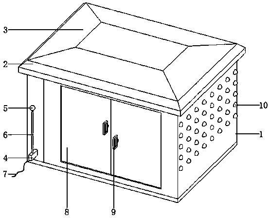
[0029] Embodiment 1: as figure 1 As shown, an anti-static interference power distribution cabinet includes a cabinet body 1, a cabinet top plate 2 is welded on the top of the cabinet body 1, a slope top cover 3 is arranged on the top of the cabinet top plate 2, and a bracket seat 4 is installed on the left side of the front end of the cabinet body 1. , the human body static elimination device is installed on the bracket seat 4, the human body static elimination device includes a spherical touch head 5 that is convenient for human body contact, the bottom of the spherical touch head 5 is provided with a vertical pole 6, and the bottom of the vertical pole 6 is connected with an antistatic ground wire 7, When in use, before entering the interior of the cabinet body 1, the staff first touches the spherical touch head 5 with their hands, and through the spherical touch head 5, the static electricity carried on the staff's body is exported through the antistatic ground wire 7, and t...

Embodiment 2

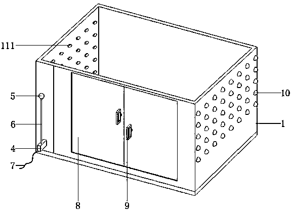
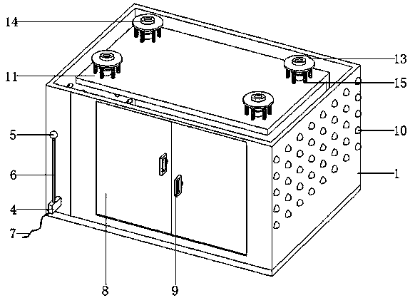
[0030] Embodiment 2: as figure 1 , image 3 and Figure 4As shown, an anti-static interference power distribution cabinet includes a cabinet body 1, a cabinet top plate 2 is welded on the top of the cabinet body 1, a slope top cover 3 is arranged on the top of the cabinet top plate 2, and a bracket seat 4 is installed on the left side of the front end of the cabinet body 1. , a human body static elimination device is installed on the bracket seat 4, a cabinet door 8 is arranged in the middle of the front end of the cabinet body 1, a handle 9 is installed on the cabinet door 8, and a compression structure is arranged at the rear end of the handle 9, and the left and right sides of the cabinet body 1 are provided with There are ventilation holes 111, the outer walls of the left and right ends of the cabinet body 1 are bonded with rainproof shells 10, the inside of the cabinet body 1 is installed with a power distribution frame 11, and the surface of the power distribution frame...

Embodiment 3

[0031] Embodiment 3: as Figure 5 and Figure 6 As shown, an anti-static interference power distribution cabinet includes a cabinet body 1, a cabinet top plate 2 is welded on the top of the cabinet body 1, a slope top cover 3 is arranged on the top of the cabinet top plate 2, and a bracket seat 4 is installed on the left side of the front end of the cabinet body 1. , the human body static elimination device is installed on the support seat 4, a cabinet door 8 is arranged in the middle of the front end of the cabinet body 1, a handle 9 is installed on the cabinet door 8, and a compression structure is arranged at the rear end of the handle 9, and the cabinet door 8 includes a left-handed door and a right-handed door. Open the door, the height of the handle 9 on the left-hand door and the right-hand door is inconsistent, the side of the left-hand door and the right-hand door close to each other are provided with installation holes, the pressing structure includes a top piece 91 ...


PUM


Abstract

The invention discloses an anti-static interference power distribution cabinet. The cabinet comprises a cabinet body. A slope top cover is arranged at the top of the cabinet top plate. A human body static electricity eliminating device is mounted on the bracket seat. A cabinet door is arranged in the middle of the front end of the cabinet. Handle is installed on cabinet door, and a pressing structure is arranged at the rear end of the handle. Vent holes are formed in the left and right sides of the cabinet body. Rainproof shells are bonded to the outer walls of the left and right ends of the cabinet body. A power distribution frame is installed in the cabinet body. Anti-static paint is sprayed on the surface of the power distribution frame. Buffering devices are installed at the four corners of the top and the four corners of the bottom of the power distribution frame. Supporting rods extend downwards from four corners of the top of the cabinet top plate. Heat dissipation fans are arranged on the left side and the right side in the cabinet body. By arranging the human body static electricity eliminating device, static electricity brought into the cabinet body by a human body is reduced, and by arranging the handle with the pressing structure, the space between the door plate bolt and the cabinet door is limited, the door plate bolt and the cabinet door are tightly attached, thecabinet door cannot be loosened, and the possibility that dust and winged insects enter the cabinet body is reduced.

Description

technical field [0001] The invention belongs to the technical field of electric equipment, in particular to a power distribution cabinet for preventing static electricity interference. Background technique [0002] The power distribution cabinet (box) is divided into power distribution cabinet (box), lighting distribution cabinet (box), metering cabinet (box), and is the final equipment of the power distribution system. The power distribution cabinet is an important part of the power distribution and transmission industry. It is a high-voltage or low-voltage power distribution device composed of switchgear, measuring instruments, protective appliances and auxiliary equipment assembled in a closed or semi-closed metal cabinet or on a screen width according to the requirements of electrical wiring. The switch connects or breaks the circuit. When there is a fault or abnormal operation, the circuit is cut off or the alarm is cut off with the help of the protective device. Variou...

Claims


Application Information

Patent Timeline
Patent Type & Authority Applications(China)
IPC IPC(8): H02B1/54H05F1/02H05F3/02H02B1/28
CPCH02B1/28H02B1/54H05F1/02H05F3/02
Inventor 柴宣何陈原
Owner 赣州市博通电气设备有限公司
Why Eureka
Eureka Blog
Learn More