Electrified railway traction power supply system and method based on multi-source access structure

A traction power supply system and electrified railway technology, applied in the field of railway network, can solve problems such as inability to use power supply power, affect power quality, and negative impact on electrified railway operation

Pending Publication Date: 2020-04-10
BEIJING NEGO AUTOMATION TECH
View PDF0 Cites 4 Cited by
  • Summary
  • Abstract
  • Description
  • Claims
  • Application Information

AI Technical Summary

Problems solved by technology

However, the existing power grid and the traction power supply system are closely coupled and have great mutual influence, and there are many problems, as follows:
[0003] (1) Adverse effects of the existing traction power supply system on the grid side
[0004] (1) Under the existing electrified railway traction network and power grid structure, it is impossible to use other types of power sources other than the high-voltage power grid
[0005] (2) Numerous electric phase-splitting equipment deployed along the traction network have huge investment and high operation and maintenance costs
[0006] (3) The electric locomotive is a high-power, asymmetrical, pulse-type single-phase load, which not only seriously affects the power quality (negative sequence, harmonics, power factor) of the 220kV / 110kV high-voltage power grid, but also increases the peak-shaving pressure of the power grid
[0007] (2) Adverse effects of the existing traction power supply system on the railway side
[0008] (1) The traction power supply system relies excessively on the strong high-voltage power grid, which makes it difficult and expensive to build electrified railways in areas with weak power grids (such as Sichuan-Tibet, Qinghai-Tibet, etc.), which seriously affects the promotion of my country's railway electrification technology
[0009] (2) The reliability, continuity and safety of the operation of the existing electric railway traction system depend entirely on the power grid system. Once the power grid fails, it will have a significant negative impact on the operation of the electrified railway

Method used


Image

  • Electrified railway traction power supply system and method based on multi-source access structure
  • Electrified railway traction power supply system and method based on multi-source access structure
  • Electrified railway traction power supply system and method based on multi-source access structure

Examples


Embodiment 1

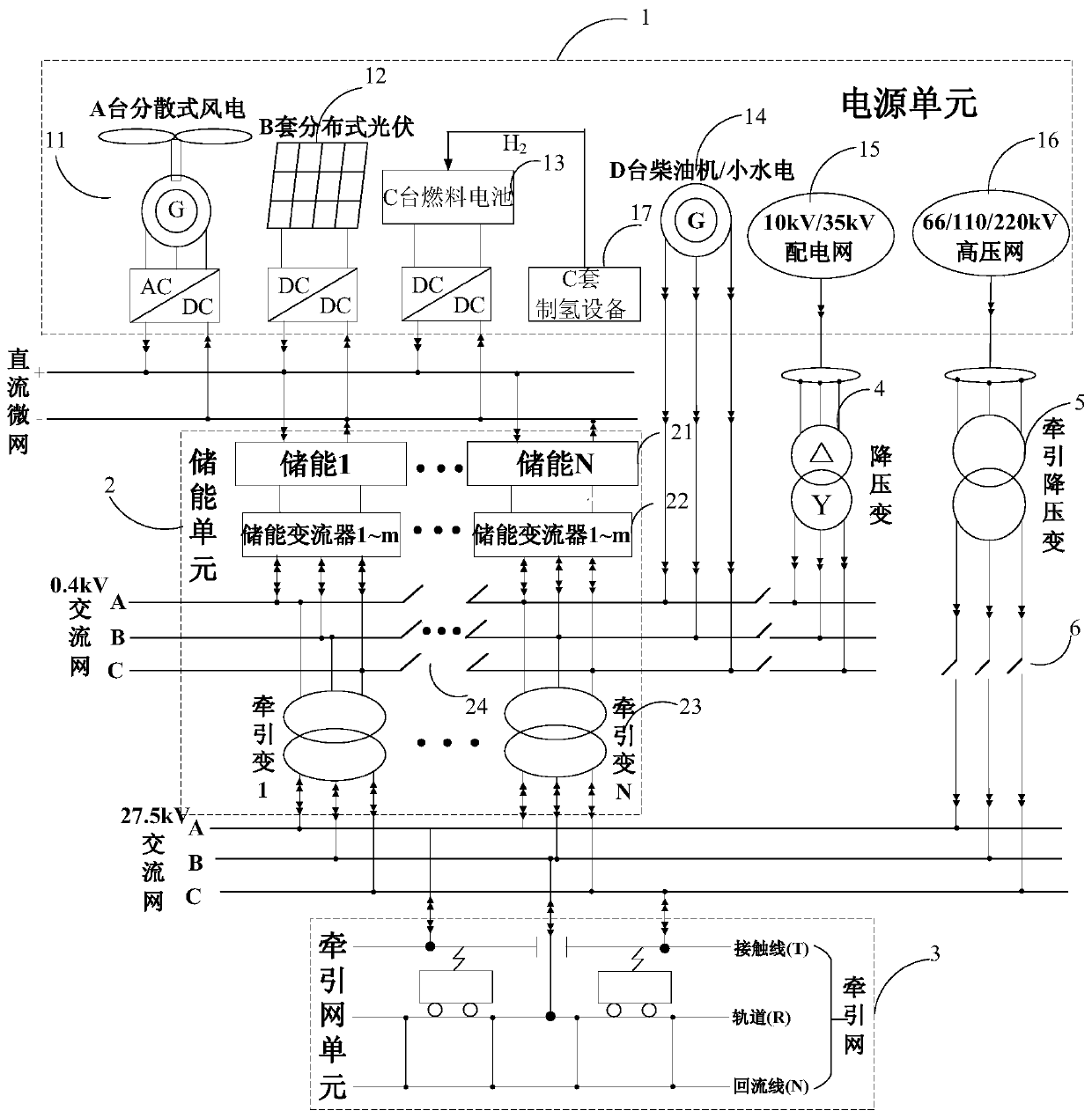
[0050] like figure 1 As shown, an electrified railway traction power supply system based on a multi-source access structure includes a power supply unit 1 , an energy storage unit 2 and a traction network unit 3 . The power supply unit 1 is a multi-type power supply unit, and various types of power supplies can be configured and flexibly combined according to local specific resource conditions and grid structure as needed. It can include A set of distributed wind turbines 11, B sets of distributed photovoltaic sets 12, C sets of fuel cell sets 13, D sets of diesel engine / small hydropower sets 14, 10 / 35kV distribution network 15 and 66 / 110 / 220kV high-voltage power grid 16 .

[0051]The energy storage unit 2 includes N sets of energy storage devices 21 , N*m energy storage converters 22 connected to the energy storage devices 21 , and N split-type traction transformers 23 for boosting. The energy storage device 21 may use one or more of an electrochemical energy storage device...

Embodiment 2

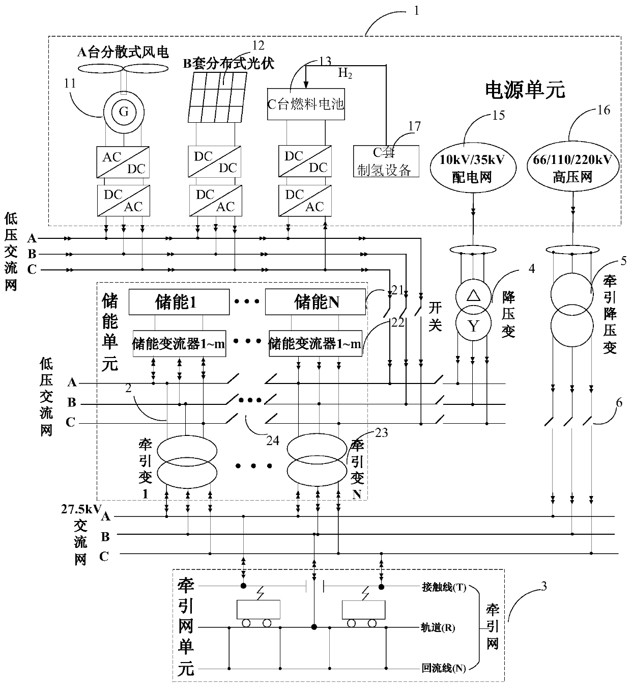
[0059] In this embodiment, as figure 2 As shown, the wind-scattered wind turbine 11 , the distributed photovoltaic group 12 , and the fuel cell group 13 form an AC micro-grid structure to coordinately charge the energy storage device 21 . The wind-scattered wind turbine 11, the distributed photovoltaic group 12, and the fuel cell group 13 are collected on the 0.7kV AC bus (the voltage level is determined by the AC outlet voltage of the wind turbine). No longer.

Embodiment 3

[0061] A power supply method for an electrified railway traction power supply system based on a multi-source access structure includes the following steps:

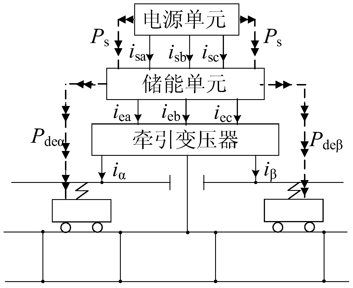
[0062] (1) Condition 1: if image 3 As shown, when the locomotive with two power supply arms is towing, the power supply unit 1 charges the energy storage unit 2 with a small current in a balanced manner, and the energy storage unit 2 generates electric energy to meet the electricity demand of the locomotive. The specific quantitative relationship is:

[0063]

[0064] In the formula: P load is the total demand power of the two locomotives; P α , P β are the power requirements of the locomotives on the two power supply arms respectively; P deα , P deβ are the powers provided by the energy storage unit 2 to the two power supply arms respectively; P s is the charging power of the power supply unit 1 to the energy storage unit; P E放 , P E充 are the actual power consumption and charging power of the energy storage un...


PUM


Abstract

The invention discloses an electrified railway traction power supply system and method based on a multi-source access structure. The system comprises a power supply unit, an energy storage unit and atraction network unit. The power supply unit at least comprises two of a distributed wind turbine generator, a distributed photovoltaic group, a fuel battery pack, a diesel engine / small hydropower station group, a power distribution network and a high-voltage power grid. The energy storage unit comprises energy storage equipment, an energy storage converter and a split traction transformer. According to the electrified railway traction power supply system and method, the excessive dependence on a high-voltage power grid is avoided. Natural endowment of wind, light, water and the like of an electrified railway construction site and other convenient power supplies can be realized. An energy supply system is flexibly formed, safe, reliable and continuous power supply of a traction power supply network under a weak net rack or even without a net rack is realized by utilizing the energy migration technical characteristics of 'full-time convergence and on-demand release' of the energy storage unit, and meanwhile, a plurality of adverse problems of an existing electrified railway traction power supply system are solved.

Description

technical field [0001] The invention relates to an electrified railway traction power supply system and method based on a multi-source access structure, and belongs to the field of railway network. Background technique [0002] Electrified railway transportation is an important support for realizing my country's regional economic integration, synergy of cross-regional economic development, and solving the imbalance of social and economic development in different regions. However, the existing power grid and the traction power supply system are closely coupled and have great influence on each other. There are many problems, as follows: [0003] (1) The adverse effects of the existing traction power supply system on the grid side [0004] (1) Under the existing electrified railway traction network and grid structure, other types of power sources other than high-voltage grids cannot be utilized. [0005] (2) The numerous electrical phase-separation equipment deployed along th...

Claims


Application Information

Patent Timeline
Patent Type & Authority Applications(China)
IPC IPC(8): H02J3/38H02J3/28H02J3/32H02J1/10B60L9/00B60L7/10
CPCB60L7/10B60L9/00H02J1/10H02J3/28H02J3/32Y02E70/30
Inventor 陈冲贾利民金成日梁立中
Owner BEIJING NEGO AUTOMATION TECH
Why Eureka
Try Eureka