
Capacitor clamping type direct-current conversion circuit

A DC conversion circuit and capacitor clamping technology, which is applied in the direction of converting DC power input to DC power output, adjusting electrical variables, and converting equipment without intermediate conversion to AC, can solve the problem of inability to ensure the reverse of the capacitor clamping DC conversion circuit. To achieve the effects of ensuring reliability, simplifying the circuit, and avoiding uneven voltage

Active Publication Date: 2020-04-10
SUNGROW POWER SUPPLY CO LTD
View PDF11 Cites 4 Cited by
  • Summary
  • Abstract
  • Description
  • Claims
  • Application Information

AI Technical Summary

Problems solved by technology

[0005] In view of this, the present invention provides a capacitor-clamped DC conversion circuit to solve the problem that the reliability of the reverse cut-off of the capacitor-clamped DC conversion circuit cannot be ensured due to the voltage equalization problem

Method used


Image

  • Capacitor clamping type direct-current conversion circuit
  • Capacitor clamping type direct-current conversion circuit
  • Capacitor clamping type direct-current conversion circuit

Examples


Embodiment approach

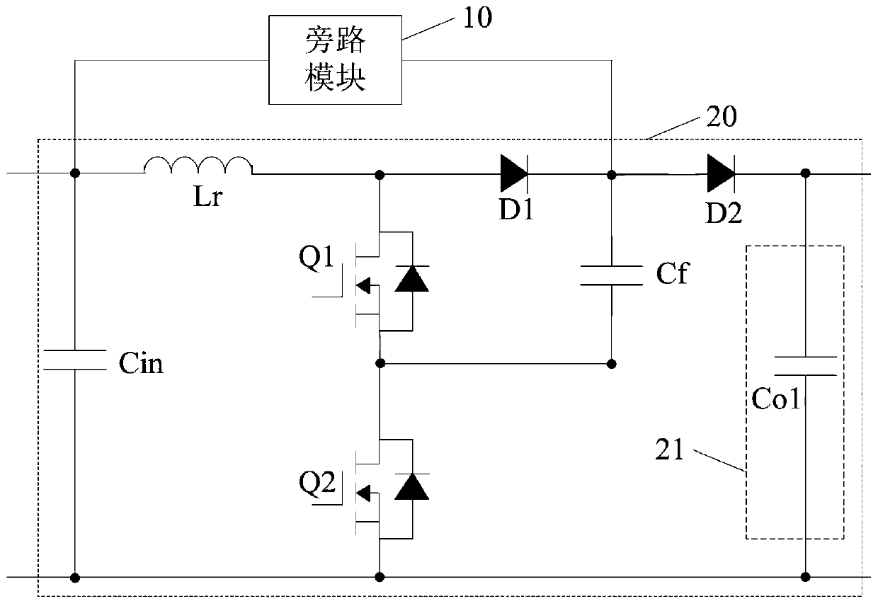
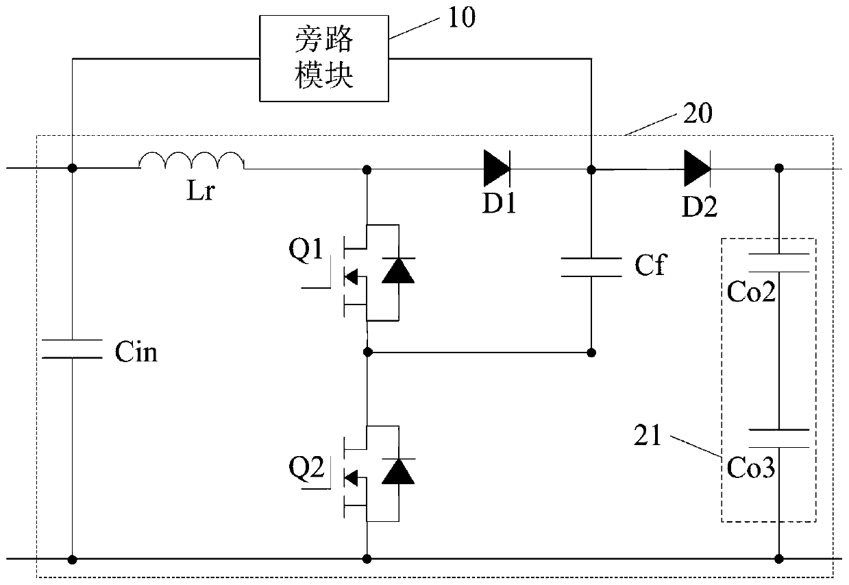
[0076] Another embodiment of the present application provides an implementation manner of a capacitor-clamped DC conversion circuit based on the above-mentioned embodiments, and further includes: a controller.

[0077] The first output terminal of the controller is connected to the control terminal of the first switching tube Q1 and the control terminal of the second switching tube Q2, and the controller is used to control the chopping operation of the first switching tube Q1 and the second switching tube Q2, so that the capacitance The clamping DC conversion circuit is in normal working condition.

[0078] If the bypass module 10 includes a bypass relay 30, the second output terminal of the controller is connected to the control terminal of the relay; road status.


PUM


Abstract

The invention relates to the technical field of power electronics, and provides a capacitor clamping type direct-current conversion circuit which comprises a capacitor clamping type boost conversion module and a bypass module, wherein the input end of the bypass module is connected with the positive electrode of the input side of the capacitor clamping type boost conversion module, and the outputend of the bypass module is connected with a connection point of two diodes on a positive electrode branch in the capacitor clamping type boost conversion module and one end of the flying capacitor; therefore, if the positive electrode and the negative electrode of the input side of the capacitor clamping type boost conversion module are short-circuited, the voltage across the two ends of the bypass module can be clamped at the voltage across the two ends of the flying capacitor, serious uneven voltage between the bypass module and a diode at the rear stage of the bypass module on the positivebranch is avoided, and the reliability of reverse cut-off of the capacitor clamping type direct-current conversion circuit can be ensured without an additional voltage-sharing circuit.

Description

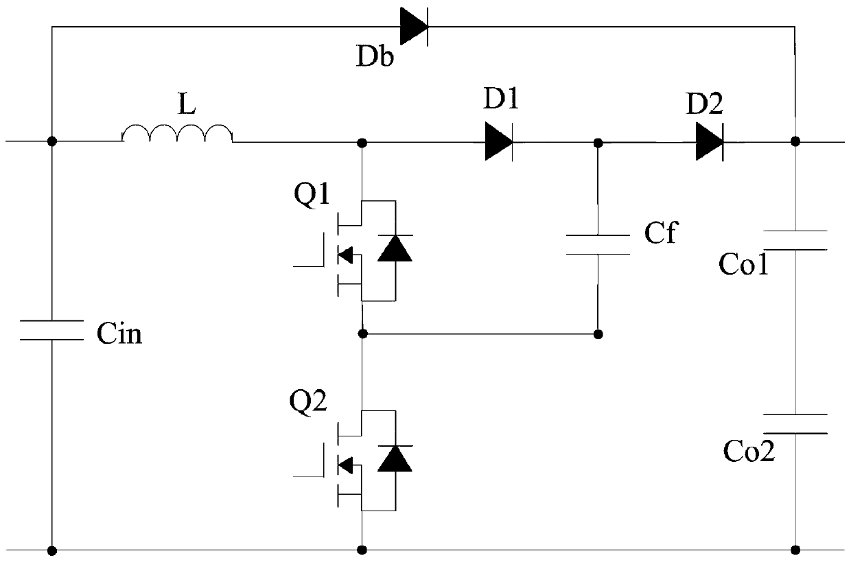
technical field [0001] The invention relates to the technical field of power electronics, in particular to a capacitor-clamped DC conversion circuit. Background technique [0002] At present, in order to improve the situation that the capacitor-clamped boost conversion module loses more energy in the process of transferring energy when it does not perform boost conversion, the existing technology usually adopts the following figure 1 Capacitor-clamped boost converter module with bypass diode shown. [0003] When the capacitor-clamped boost conversion module only performs energy transfer without boost conversion, the bypass diode Db bypasses the inductor L, the first diode D1 and the second diode D2, and the capacitor clamp The voltage on the input side of the bit-type boost conversion module is directly transmitted to the output side of the capacitor-clamped boost conversion module through the bypass diode Db, so as to reduce the loss in the transmission process. And when ...

Claims


Application Information

Patent Timeline
IPC IPC(8): H02M3/04H02M3/08H02M3/155
CPCH02M3/04H02M3/08H02M3/155
Inventor 陈鹏徐清清李晓迅
Owner SUNGROW POWER SUPPLY CO LTD
Learn More