Supercharge Your Innovation With Domain-Expert AI Agents!

Current predictive control method of pwm rectifier with dead zone compensation

A technology of current prediction and dead zone compensation, applied in the direction of converting AC power input to DC power output, electrical components, output power conversion devices, etc., can solve the problems of unstable switching frequency, low switching frequency, and simultaneous conduction, etc. Achieve the effect that the amplitude of the fundamental wave of the output voltage remains unchanged, the harmonics of the grid-side current are small, and the switching frequency is constant

Active Publication Date: 2021-05-14
SOUTH CHINA UNIV OF TECH
View PDF3 Cites 0 Cited by
  • Summary
  • Abstract
  • Description
  • Claims
  • Application Information

AI Technical Summary

Problems solved by technology

Model predictive control has the advantages of simple control structure and fast dynamic response, but there are also problems such as unstable switching frequency, large amount of calculation, high harmonic content of grid-side current, and simultaneous conduction of two switching tubes of the same bridge arm.
[0003] At present, the predictive control of single-phase PWM rectifiers has fixed-frequency predictive power control, but this method has a large amount of calculation and complex control, and there is only one zero-switching state in one sampling period, and the harmonic suppression is not ideal due to low switching frequency. In the process of model derivation, the influence of dead zone is not considered, which makes the model inaccurate

Method used


Image

  • Current predictive control method of pwm rectifier with dead zone compensation
  • Current predictive control method of pwm rectifier with dead zone compensation
  • Current predictive control method of pwm rectifier with dead zone compensation

Examples


Embodiment

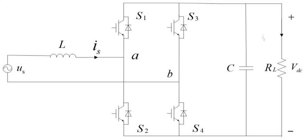
[0048] figure 1 It is a single-phase PWM rectifier circuit diagram, the PWM rectifier circuit includes 4 MOS tubes, filter inductor L, voltage stabilizing capacitor C and resistor R L , where the four MOS transistors are divided into two groups, two MOS transistors in each group are connected in series and then connected in parallel to form the first bridge arm and the second bridge arm, and one end of the filter inductor L on the input side is connected to the midpoint of the first bridge arm, The other end is connected to the input voltage, the other end of the input voltage is connected to the midpoint of the second bridge arm, the voltage stabilizing capacitor C and the resistor R L After parallel connection with the first bridge arm and the second bridge arm, the voltage stabilizing capacitor C and the resistor R L Parallel connection constitutes the output side of the single-phase PWM rectifier circuit.

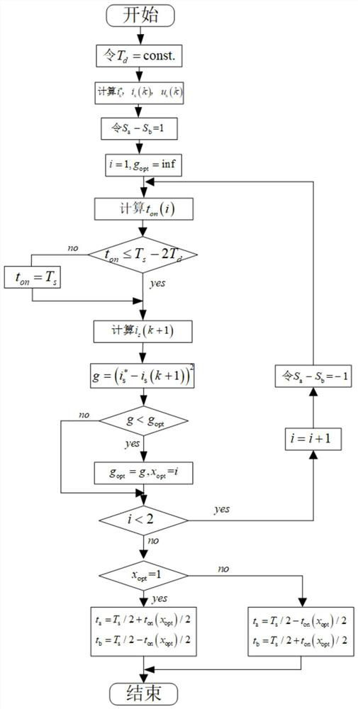
[0049]according to figure 2 The disclosed flow chart of the P...


PUM


Abstract

The invention discloses a PWM rectifier current prediction control method including dead zone compensation. The control method includes the following steps: using the discrete mathematical model of the rectifier circuit as the prediction model at k+1 time; selecting a Effective switching state and two zero-switching states, and the action time of the two zero-switching states is the same; given the dead time added when the upper and lower switching tubes of the same bridge arm switch, calculate the different switching states according to the direction of the input current The optimal action time and the corresponding predicted current value; Substituting the relevant parameters into the objective function, and selecting the effective switching state that minimizes the objective function as the effective switching state of the next cycle. The invention realizes the predictive control of the fixed-frequency current, adds dead zone compensation, effectively reduces the harmonic content of the input current, and improves the reliability of the system operation.

Description

technical field [0001] The invention relates to the technical field of PWM rectifier control, in particular to a PWM rectifier current prediction control method including dead zone compensation. Background technique [0002] With the increasingly serious energy crisis and environmental problems, the research of new energy technology has received more and more attention. In small and medium power applications, PWM rectifiers are widely used. Model predictive control has the advantages of simple control structure and fast dynamic response, but there are also problems such as unstable switching frequency, large amount of calculation, high harmonic content of grid-side current, and simultaneous conduction of two switching tubes of the same bridge arm. [0003] At present, the predictive control of single-phase PWM rectifiers has fixed-frequency predictive power control, but this method has a large amount of calculation and complex control, and there is only one zero-switching s...

Claims


Application Information

Patent Timeline
Patent Type & Authority Patents(China)
IPC IPC(8): H02M7/219H02M1/12H02M1/38
CPCH02M1/12H02M1/38H02M7/219H02M1/0009
Inventor 康龙云周海兰张健彬于玮
Owner SOUTH CHINA UNIV OF TECH
Features
  • R&D
  • Intellectual Property
  • Life Sciences
  • Materials
  • Tech Scout
  • Unparalleled Data Quality
  • Higher Quality Content
  • 60% Fewer Hallucinations
Learn More