Secondary separation mechanism of harvester

A secondary separation and harvester technology, applied in agricultural machinery and tools, threshing equipment, applications, etc., can solve the problems of inability to improve grain retention rate, inability to separate cleanly, and waste of grain, etc., and achieve simple structure, high operating efficiency, The effect of reducing waste

Pending Publication Date: 2020-04-14
HUNAN NONGFU ELECTROMECHANICAL
View PDF0 Cites 1 Cited by
  • Summary
  • Abstract
  • Description
  • Claims
  • Application Information

AI Technical Summary

Problems solved by technology

[0002] The harvester was invented by Cyrus McCormick; and the harvester is an integrated machine for harvesting crops; it completes harvesting, threshing, and concentrates the grains into the storage bin, and then transports the grain through the conveyor belt On the transport vehicle, it can also be manually harvested, laying the stalks of rice, wheat and other crops in the field, and then picking up and threshing with grain harvesting machinery; crop harvesting machinery for harvesting rice, wheat and other cereal crops and straw; including Harvesters, windrowers, balers, grain combine harvesters, and grain threshers, etc.; grain harvesting machinery is developed on the basis of various harvesting and threshing tools, and in the process of harvesting, a separation mechanism is required. The rice is separated, but when the existing harvester harvests the rice and wheat, the grain and the grass part separated by the drum cannot be separated twice, which makes a small part of the rice still exist on the rice grass, which cannot be separated cleanly, and a lot of food is wasted. Unable to improve grain retention

Method used


Image

  • Secondary separation mechanism of harvester
  • Secondary separation mechanism of harvester

Examples


Embodiment Construction

[0013] The following will clearly and completely describe the technical solutions in the embodiments of the present invention with reference to the accompanying drawings in the embodiments of the present invention. Obviously, the described embodiments are only some, not all, embodiments of the present invention. Based on the embodiments of the present invention, all other embodiments obtained by persons of ordinary skill in the art without making creative efforts belong to the protection scope of the present invention.

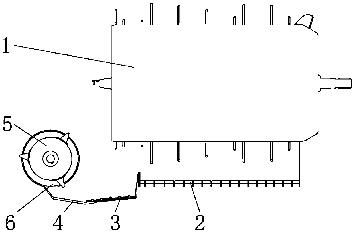
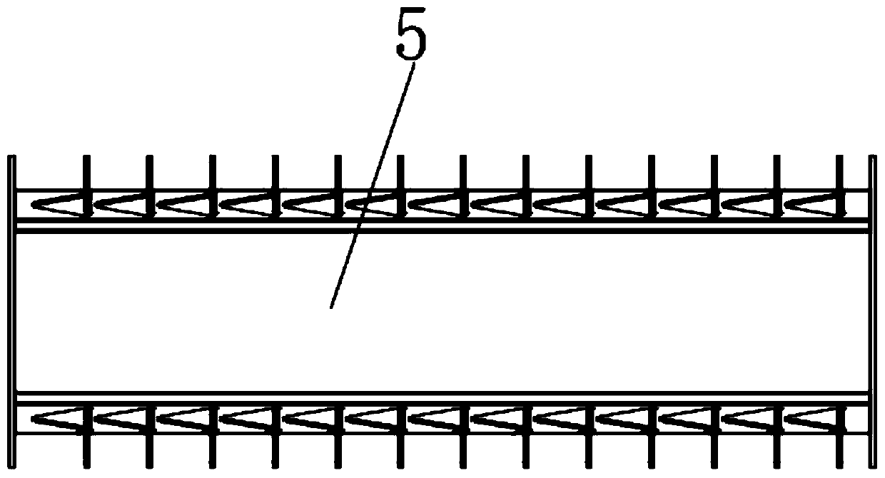
[0014] see Figure 1-2 , the present invention provides a technical solution: a secondary separation mechanism for a harvester, including a drum 1, a vibrating screen 2, a grass feeding plate 3, a support plate 4, a separation cylinder 5 and a feed port 6, and the outer wall of the bottom end of the drum 1 A vibrating screen 2 is installed on the top, and the drum 1 is located on the outer wall of the vibrating screen 2. A grass feeding plate 3 is installed on...


PUM


Abstract

The invention discloses a secondary separation mechanism of a harvester. The secondary separation mechanism of a harvester comprises a roller, a vibrating screen, a straw feeding plate, a supporting plate, a separation tube and a feeding opening, wherein the vibrating screen is arranged on the outer wall of the bottom end of the roller; the straw feeding plate is arranged in a position, positionedon the outer wall of the vibrating screen, of the roller;; the supporting plate is connected onto the outer wall of the bottom end of the straw feeding plate through screw bolts; the separation tubeis rotationally arranged on the outer wall of one side of the roller; the feeding opening is formed in the outer wall of the bottom end of the separation cylinder; one end of the straw feeding plate is inserted into and connected with the inside of the feeding opening; and the roller and the separation tube are in a cylindrical shape. The secondary separation mechanism of the harvester is used forperforming secondary separation on grain particles and rice and wheat straws when the harvester is used for harvesting rice or wheats, so that the grains and the straws can be more cleanly separated;the retention rate is improved; the entrainment loss of grains is reduced; in addition, the structure is simple; the operation efficiency is high; the grain and straw separation effect is good, so that the grain waste is reduced; and the economic benefits of farmers are increased.

Description

technical field [0001] The invention relates to the technical field of harvester auxiliary equipment, in particular to a harvester secondary separation mechanism. Background technique [0002] The harvester was invented by Cyrus McCormick; and the harvester is an integrated machine for harvesting crops; it completes harvesting, threshing, and concentrates the grains into the storage bin, and then transports the grain through the conveyor belt On the transport vehicle, it can also be manually harvested, laying the stalks of rice, wheat and other crops in the field, and then picking up and threshing with grain harvesting machinery; crop harvesting machinery for harvesting rice, wheat and other cereal crops and straw; including Harvesters, windrowers, balers, grain combine harvesters, and grain threshers, etc.; grain harvesting machinery is developed on the basis of various harvesting and threshing tools, and in the process of harvesting, a separation mechanism is required. Th...

Claims


Application Information

Patent Timeline
Patent Type & Authority Applications(China)
IPC IPC(8): A01F12/44
CPCA01F12/446
Inventor 廖郴鹏李华庚周艳明邓学清廖增才何志伟首元锋黄俊维
Owner HUNAN NONGFU ELECTROMECHANICAL
Why Eureka
Try Eureka